This thread has been locked.

If you have a related question, please click the "Ask a related question" button in the top right corner. The newly created question will be automatically linked to this question.

Incorrect parametric search values in error

Expert 1961 points
Other Parts Discussed in Thread: SN74AHC1G02-EP, SN74AHC1G126-EP, SN74AHC1G86-EP, SN74AHC04, SN74CBT1G125, SN74LVC2G34, SN74LVC3G34, SN74CBT3257C, LMH6321, SN74HC244, SN74LVC1G34, CD74ACT541, SN74LVC1G3157

While searching for a suitable part for my application, I found some parametric search values that were not correct.  For example, in the Little Logic section, the max current is listed as +/- 50 mA for the SN74AHC1G02-EP, SN74AHC1G126-EP, and SN74AHC1G86-EP.  But I think that it should be +/- 8 mA at 5V (+/- 50 uA would be at 2V).  In the Buffer/Driver/Transceiver section, I found the SN74AHC04 which is also wrong in the same way, but the data sheet is also wrong.  It incorrectly states the IOH and IOL current as +/- 50 mA @ 2V.  However the same data sheet also lists VOH and VOL with the correct value of IOH/IOL of 50 uA.  I think there are many more parts that the parametric search that incorrectly list the drive as +/- 50 mA.

I am looking for a buffer to drive a 0 to 5V PWM signal into 50 Ohms.  I don't think there are any logic family ICs that fit that need.  If there are, please let me know which ones.  If not, what family of ICs would be best for that application?  Video amplifiers? Op-amps? Motor Drivers?

Thanks,

Greg

  • Sorry, I forgot to list the frequency of the PWM. It should be a max of about 80 kHz, but since the edge rates should be fairly steep ("digital"), the required bandwidth would be higher than that.
  • What value of what characteristic are you looking for? Drive strength? Output impedance?

    For single-gate devices, the LVC family has the highest drive strength (32 mA at 5 V). You could combine multiple outputs to get more.
    Alternatively, the SN74CBT1G125 bus switch has a maximum resistance of 7 Ω.

  • Hi Clemens. Thank you for the suggestions. I don't think the SN74CBT1G125 bus switch will work because the drive needs to be push-pull in order to preserve the PWM duty cycle. But I am very interested in combining multiple outputs if that is possible. I have read about this on the web, but have shied away from it because I never read anything from an authoritative source. If TI will tell me it is OK to do, that would be awesome! From what I have read, the recommendation has been to use a multi-gate package to ensure the timings for each gate are the same. Mismatches will cause glitches as one driver fights another when they change state.

    I am looking for a driver that can drive a 50-Ohm load effectively. I realize the output won't quite reach 5V, so an actual output of about 4 to 4.5V or so would be acceptable. I guess that means the output current would be 80 mA if the voltage was 4V across a 50-Ohm load. Which means the output impedance would be 12.5 Ohms. If the output was 4.5V, then the current would be 90 mA and the output impedance would be 5.6 Ohms.
  • You could combine two SN74CBT1G125s two switch to either VCC or GND.
    (The SN74CBT1G125 is essentially just a MOSFET; you could build your own driver with two bigger MOSFETs.)

    As for combining CMOS outputs: the output MOSFETs are run in the region where they have a positive temperature coefficient, so if any part is running hotter, it will increase its resistance so that its current is reduced. So this is safe, and allowed; see the FAQ, or figures 37/38 of HCMOS Design Considerations (SCLA007).
    (Use SN74LVC2G34 or SN74LVC3G34.)

  • Thank you very much for your help Clemens. I think this is going to be a great solution.

    Now I understand what you were suggesting with the bus switch. I'm glad to hear the MOSFETs are run in the region where they have a positive temperature coefficient. Does that mean that the output might be a little noisier at first? And as the PWM runs for a while, the resistances even out as they heat up? I wasn't thinking about power and thermal runaway. I was thinking more about signal integrity and voltage spikes.

    What do you think of the SN74CBT3257C? Could the four A-terminals be connected in parallel, the B1-terminals connected to VCC, and the B2-terminals connected to ground? Thank you for the link to the FAQ on combining outputs. I think this chip qualifies because it meets both requirements of being three-state logic and being on the same chip. I like this chip because it has a single control terminal to switch between 0V and 5V, which means there shouldn't be any shoot-through from +5V to ground because both switches could not be on at the same time. Combining 4 channels in parallel would leave plenty of headroom and I wouldn't need to worry about power dissipation over temperature. With such a low on-resistance, would a few Ohms of resistance in each supply lead be advised?
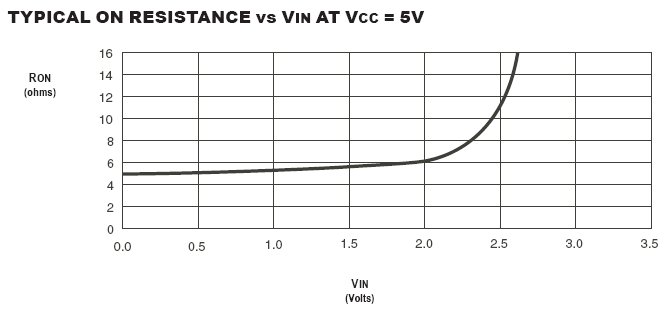
  • It looks like there are similar parts to the SN74CBT3257C available from other vendors.  I was looking for more information on this chip because the data sheets are a little thin compared to other chips in general.  What I found is that everyone specs the on-resistance with Vin set to 2.4V.  One data sheet from IDT shows a graph of on-resistance vs. Vin at VCC=5V.  This is what it looks like:

    The resistance goes asymptotic pretty quickly after 2.5V.  So I'm doubtful about the SN74CBT3257C working as a PWM driver.

  • Temperature typically isn't a problem for logic chips; I've mentioned its effects only because they ensure that you can combine outputs without one device hogging all the current. I don't think that temperature changes will have any noticeable effect on the signal.

    The SN74CBT3257C datasheet does not mention break-before-make, so shoot-through might be possible, for a very short time.

    Why do you go to great lengths to reduce the output impedance (1.5 Ω), and then again add resistors? Please choose which output impedance you actually want. (If you want to reduce noise, use more decoupling capacitance, or add inductors/capacitors to the output.)
  • I posted a reply to my last post before you have replied, but the website blocked it for moderation. It would be nice if they explained why it happened. Not sure if this one will go through or not.

    In my post I said that I had looked at similar devices from other vendors, looking for more info because the data sheet is a little thin on application information. I noticed that every vendor was specifying on-resistance at 2.4V. IDT's data sheet showed a graph, and the resistance started rising at higher voltages and going asymptotic at about 2.5V. So I don't think the SN74CBT3257C would have worked anyway. I just looked at the data sheet for the SN74CBT1G125, and I see its on-resistance is also specified at Vin = 2.4V. It is 10 Ohms with only 15 mA of current.

    My objective wasn't to reduce the output impedance as much as it was to remain well within the maximum current specs. That part only cost 18 cents, so quadruple the channels wasn't an issue. The only reason for adding the resistors was to protect against the short circuit condition.

    I would be happy with an output impedance that is 5 Ohms or less. That would yield 4.5V when driving 50 Ohms, which should be good. Lower impedance isn't really necessary, and at some point the short circuit current is going to be quite large.

    I've been following your suggestion about building my own driver with bigger MOSFETs. I've been simulating a simple inverter and having fun finding a complementary MOSFET pair that gives a nice result.

    Another solution I found is the LMH6321, which is quite expensive. But the adjustable current limit feature is nice.

    This thread was not intended to run on like this. Initially I was expecting someone would tell me where to post my question. I was surprised that there were solutions in the Logic family of parts. Maybe someone from TI can move this thread or rename it.

    Thank you very much for your help. You have been very helpful!
  • By the way, I know the LMH6321 will require a bipolar supply, and more than 5V as well. It would be a lot nicer to have a simple digital solution, so I'll only use that part if I can't come up with anything else.
  • Hey Greg,

    Just to chime in as a TIer -- Clemens is always full of fantastic information and we love having him on the forum. I think you'll do fine with his suggestions.

    We greatly appreciate you pointing out the errors on the parametric search and datasheets. Unfortunately, the parametric search database is _full_ of errors right now. We have an internal project this year to not only fix the errors, but also add more useful data (for example, having 3-state, open drain, and push-pull outputs as a searchable column). There's a limited number of apps engineers working on it and we have many parts, so be patient with us please :)

    You mentioned that you'd like to us to bless the paralleling of multiple buffers - we often tell people to do this for added drive strength. I would recommend only doing it inside a single chip due to timing issues (ie don't parallel 4 separate SN74LVC1G34's - use 4 channels of an SN74HC244 instead)

    Please feel free to post any time on the Logic forum. If we feel that your post is better answered in another area, we will politely let you know and move it on over. Have a great day!
  • Thanks Emrys. Yes, Clemens has been very helpful. Thanks for offering your advice too, and for letting me know that you are well aware of the problems with the parametric search. Is there a forum or e-mail address where discrepancies/errors can be reported? You probably don't want to hear much until your internal project has been completed this year. I looked a little bit and didn't see one, which is why I started the forum posting. It also gave me the opportunity to get pointed in the right direction for the task at hand.

    Regarding combining outputs from the same chip, the Logic FAQ says it can be done with the following types of chips: "Three-state logic and open-drain logic outputs". I want to make sure that there aren't any stipulations with outputs of the "three-state logic" type. I'm hoping that it is OK to parallel three-state outputs because of how that type of output is designed, rather than how it is used. For example, is there a stipulation that the output must be tri-stated before switching from high to low or vice versa? Hopefully the output can remain on all of the time, and the output state can be switched rapidly. Since I want to drive a large amount of current (100 mA), the HC family is not going to have enough drive. How about a chip like the CD74ACT541? The absolute max current rating through VCC or GND is +/- 200 mA, so I wouldn't be violating that spec. Could I tie all 8 channels in parallel? I can protect the chip from frying by using an eFuse in case the output is shorted.

    Thank you for your help and have a great weekend.
  • See the "Site Support & Feedback" link below.

    I think that FAQ entry answers the wrong question, i.e., whether it is possible to combine outputs of different devices that might output different values. In that application, the high-impedance state would be needed to avoid bus contention.
    For just getting more current, you can use any device with push/pull outputs, as long as all outputs are guaranteed to output the same value.

    I proposed bus switches because the load current would not have to go through the VCC/GND pins. But the CD74‍ACT541 looks as if it would work fine.

  • The resistance goes asymptotic pretty quickly after 2.5V.  So I'm doubtful about the SN74CBT3257C working as a PWM driver.

    A FET is switched on by the gate-to-source voltage difference, so a single FET is suitable only for low signal voltages, or for open-drain applications.

    You'd have to use an analog switch (which combines an N-channel FET and a P-channel FET to get almost-constant resistance over the entire voltage range), such as the SN74LVC1G3157.

  • Clemens Ladisch said:

    See the "Site Support & Feedback" link below.

    Thanks.  I should have been able find that.  Next time I'll know.

    Clemens Ladisch said:

    I think that FAQ entry answers the wrong question, i.e., whether it is possible to combine outputs of different devices that might output different values. In that application, the high-impedance state would be needed to avoid bus contention.

    LOL, "See the "Site Support & Feedback" link below". (your turn)


    Clemens Ladisch said:

    For just getting more current, you can use any device with push/pull outputs, as long as all outputs are guaranteed to output the same value.

    I proposed bus switches because the load current would not have to go through the VCC/GND pins. But the CD74‍ACT541 looks as if it would work fine.

    If that is true, then that would be great!

  • A FET is switched on by the gate-to-source voltage difference, so a single FET is suitable only for low signal voltages, or for open-drain applications.

    You'd have to use an analog switch (which combines an N-channel FET and a P-channel FET to get almost-constant resistance over the entire voltage range), such as the SN74LVC1G3157.

    Thanks for explaining that.  Makes a lot of sense.

  • Could someone from TI please confirm whether it would be OK to parallel the outputs of a CD74ACT541? The load will be 50 Ohms, so the total current through the VCC pin will be less than 100 mA. Clemens, thank you for your respected advice. But please don't take it personally. I'd just like to have someone from the company that is selling the chips comment on it too. Thanks, Greg
  • Hey Greg,

    The CD74ACT541 is actually designed to drive 50 ohm transmission lines with a single output. You can parallel the outputs, but it is likely unnecessary.

    In my experience, going overboard with drive current with logic can be very detrimental to signal integrity. I would recommend building a prototype of your board with the option for paralleling.
  • Hi Emrys,

    The data sheet says that it is designed to drive 50-Ohm transmission lines, but it also says that 1 output should only be turned on for a maximum of a 1-second duration. It needs to be capable of being on indefinitely (100% PWM duty cycle). All of the outputs in parallel would even the load to 100 mA/ 8 = 12.5 mA each. If a logic family chip is not the best choice, what family is the best driver for driving 50-Ohm loads across a cable?

    Thanks, Greg
  • Those values are intended to show what happens when you drive a 50 Ω line with a single output. Combining multiple outputs should work just fine (but in any case, the huge current is likely to cause noise on the power supply lines).

    It might be a better idea to build your own driver with discrete MOSFETs. (The resulting overall current will be the same, so the same noise considerations apply.)

  • Thank you Clemens. Since the current is the same whether I build my own driver out of discrete MOSFETs or use the CD74ACT541, might there be a consideration for the package size? Would the large package size of the CD74ACT541 have more inductance in the supply leads which would cause a degradation in signal integrity? A discrete solution could be packed together tightly and I'm thinking the packages would have less inductance. I expect there would be a lot of shoot-through, but enough capacitance (ceramics) should be able to supply the current needed during the transition.
  • AN-1205 Electrical Performance of Packages (SNOA405) has the typical lead inductances. I do not know how much these would actually matter.

  • Thanks for the link to that application note. Lots of good information in there. If I use the TSSOP package, the distance from the power leads to the chip are pretty short. So I'm thinking that it probably wouldn't matter. I'll read that document later today.

    I think I will breadboard some circuits and see how they behave.
  • Hi Emrys,

    I selected your answer from early in the thread as the correct answer to the title of the thread. Would it be possible to move part of this thread to a new topic? If it isn't worthwhile then don't worry about it. Clemens has been very helpful and I'd like to select his answer too. Maybe it would be better to rename the thread and delete the stuff about the parametric search having incorrect values.

    Thanks to both of you. I'll let you know if I have any interesting results.

    Greg
  • Thanks Greg,

    I can spike out a thread to multiples, but this seems to remain on the same topic the whole time to me. You can label as many posts as you like as 'Answer's -- feel free to label Clemens' posts as well. When the post is found by others in future, only the original post and the 'answer' posts will be shown.