Part Number: CD74HCT4046A
Hi,
I use PC2 of CD74HCT4046 as the phase detector, PC2Out output drives a VCTCXO after RC filtering.
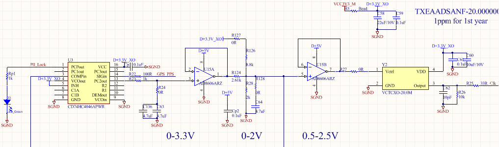
According to the datasheet, PC2out is an edge-triggered JK flip-flop output.
The positive and negative pulses are output when the Sigin and Compin edges are relatively advanced and delayed respectively, and the remaining states remain unchanged.

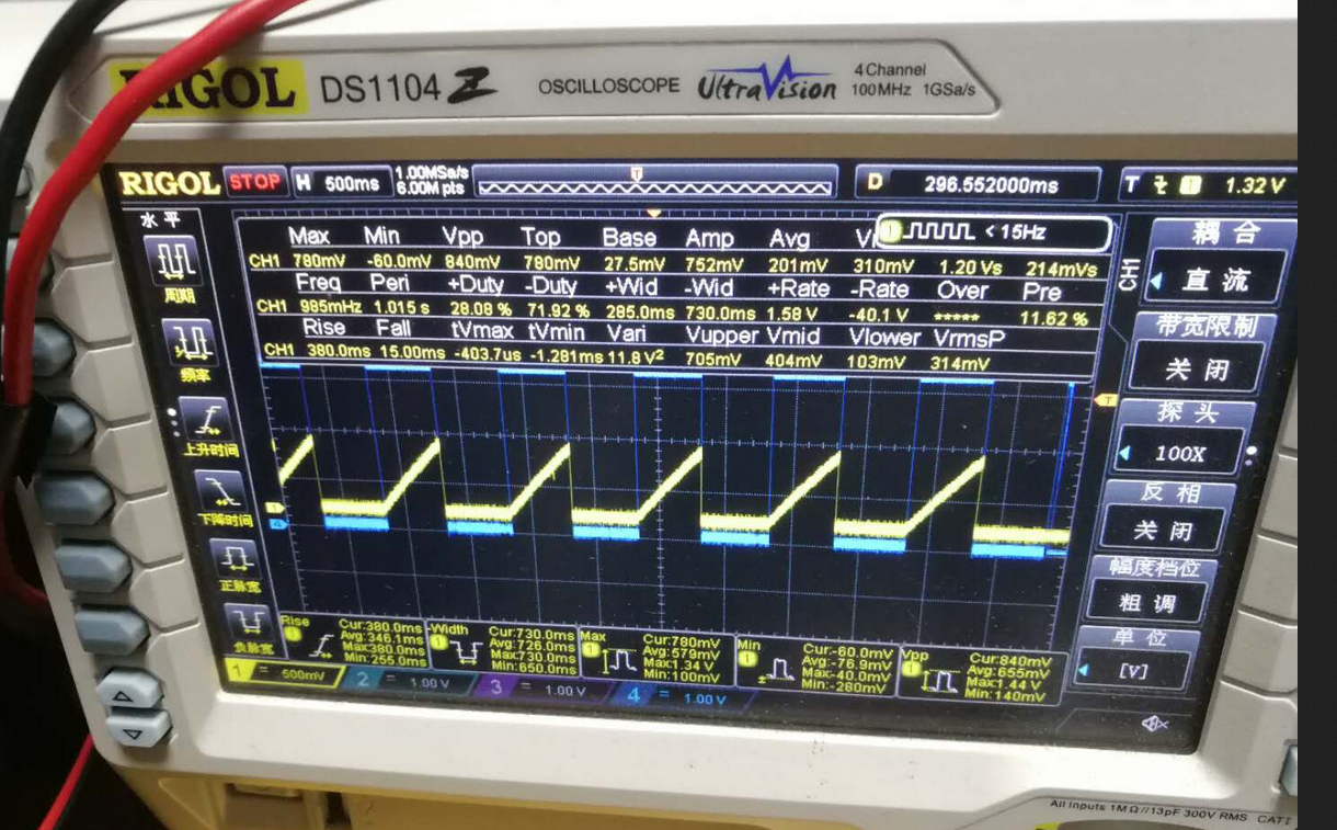
However, in the actual circuit test, the PC2Out pulse output is normal. In the high-impedance state, PC2Out should theoretically remain unchanged, but the actual result is that PC2out falls to 0 level in the high-impedance state, so that the accumulation of phase error cannot be formed. Finally, only a very small level is obtained after filtering, and the VCTCXO does not normally drive the frequency adjustment to form a phase lock on the GPS signal.
Blue is PCPout waveform and yellow is PC2out waveform