This thread has been locked.

If you have a related question, please click the "Ask a related question" button in the top right corner. The newly created question will be automatically linked to this question.

SN74GTL1655: The output spur during powering up

Part Number: SN74GTL1655

Hi team,

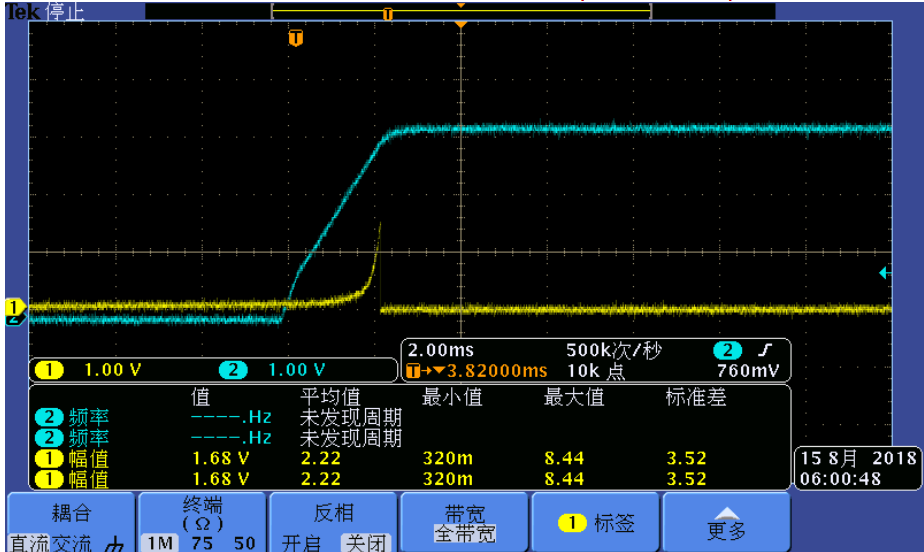
My customer find when they power up the SN74GTL1655, there is a spur occur when the supply voltage go to about 70% VCC.(see below)

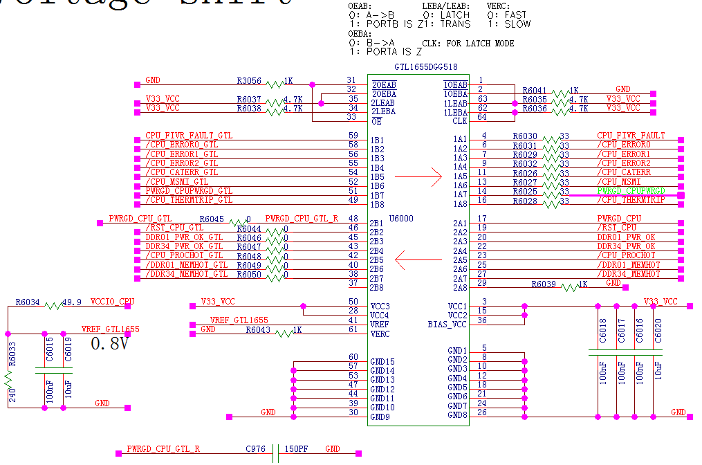
The blue on is the supply voltage, the yellow one is the output signal in 1A.(below is the schematic)

The rising time of the supply is about 2ms.

My customer connect the 1A to CPLD, and there is 4.7K pull up resistor and the input cap of the CPLD pin is about 5pf.

So for the spur, please help to answer below questions:

1. is it a normal performance of the part during the power up? If not, what may be the cause for the spur?

2. Can you help to analyze if there is method to eliminate the spur?

Lacey

Thanks a lot!

  • Hi Lacey,
    I've asked our translation expert to take a look at this. You should expect a response within 24 hours.
  • Hi Lacey,

    This device has internal circuit to support power up 3 state which ensures high impedance on the IO ports until Vcc reaches 50%.

    The device should not have an external resistor connected since this internally has bus hold circuitry. Is there a way to disconnect / remove the resistors and check the implementation again?

    what is the status on the corresponding input pins? are they held at gnd or left floating or connected through a pull-up resistor as well? I believe the driver is trying to go high but internally it recognizes the input as low and pulls it down eventually.

  • Hi ShreyasRao,

    Thanks so much for your reply.

    Customer remove the external pull up resistor and the spur disappear.

    So can you help to check below questions:

    1. How does the external pull up resistor affect the bus hold circuitry to show the spur?

    2. For the A port, we don't need to use the external pull up resistor, and does the output high voltage of the A port refer to the VCC?

    3. Because the B port is the OD port, so we need external pull up resistor? is it correct?

    Lacey

    Thanks a lot!

  • Hi Lacey,

    Glad to know that the spur disappears removing the pull-up resistors.
    As i mentioned before, the bus hold circuitry tries to keep the state low, but the pull-up is forcing the line high. The input when low will force the line low again once the Vcc reaches a state to disable the power up 3 state circuit.
    B port would require a pull-up as it is open drain.