This thread has been locked.

If you have a related question, please click the "Ask a related question" button in the top right corner. The newly created question will be automatically linked to this question.

SN74AUP1G04: SN74AUP1G04 signal shaping

Part Number: SN74AUP1G04
Other Parts Discussed in Thread: SN74LVC1GU04, , SN74AUP1G14

Hello,

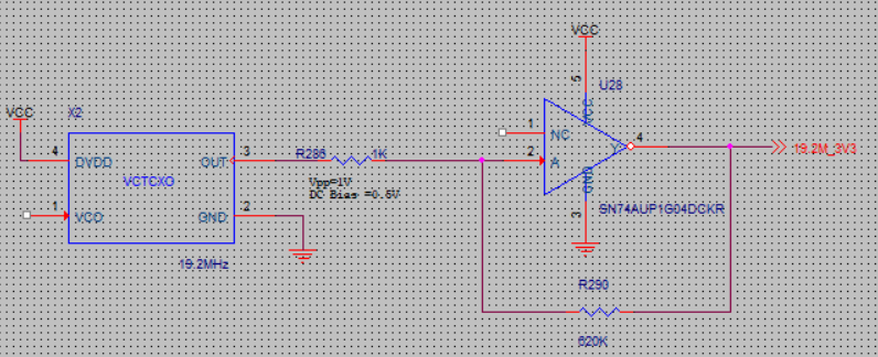
We are using this inverter to achieve signal shaping, both the power rail is 3V, could you pls help review this circuit, and let me know if any suggestion.

thank you.

  • Hi Leo,
    Your question is on the SN74AUP1G04, but your schematic has the SN74LVC1GU04. Which device do you plan to use?

    Can you provide details regarding the signal coming out of the VCTCXO?
    I see that it's labelled as 19.2 MHz.
    Do we know the DC bias?
    Shape of the waveform?
  • Hi Emrys,

    It should be SN74AUP1G04, I also attached the schematic:

    And the VCTCXO output signal:

  • I would recommend adding a series capacitor (0.1uF) between the output of the VCTCXO and the resistor R286. This will allow for self-biasing of the SN74AUP1G04 and the best chance for a good output. Otherwise the input will be too low for the device to recognize. One down-side of this is that the device will output ~1/2Vcc when the oscillator is off. I would add a Schmitt-trigger buffer or inverter after that to square the signal and prevent invalid signals from continuing through the system (SN74AUP1G14 or 17)

    For this type of amplification, I would typically recommend an unbuffered inverter like the SN74LVC1GU04, or even better an op amp or comparator.
  •  Hi Emrys,

    Pls help review below circuit, to see if any comments.

    Thank you.

  • Hi Leo,

    I tested this setup in my lab and got the following results:

    With your configuration (SN74LVC1GU04 with 620k feedback and 1k input resistor).

    You can see here that the input (green) is amplified, but only by about 3x.

    I shorted out the 1k input resistor and got this result:

    Here you can see that the output nearly reaches both rails, which is ideal for this wave-shaping circuit.

    I would recommend removing the 1kohm input resistor, and then your circuit should work.

  • Hi Emrys,

    Thank you for your suggestion.