This thread has been locked.

If you have a related question, please click the "Ask a related question" button in the top right corner. The newly created question will be automatically linked to this question.

SN74HC595: the problem of usage

Part Number: SN74HC595

Dear all:

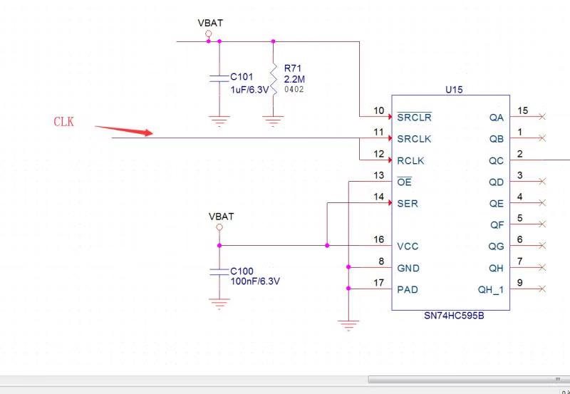
      I use SRCLR=1,OE=0,SER=1,SRCLK is connected to RCLK

I want to achieve the function is to trigger a CLK high level, the output of the first high level;Then trigger a CLK high level, the output second high level;And so on

The circuit diagram is as follows:

But now I manually contact with VBAT for CLK, and then release.The output is all high. I connected the LED light at the output end, and the LED light is all bright.

Why is that? Can you give me some advice?

I use the domestic 595, with this circuit and this method test, the result is to trigger a high level, the output of a high, and so on

  • Timsen,

    I presume you are using the HC595 to trigger the LEDs at the output.
    There is a reference design which does exactly the same. Please refer to it below:
    www.ti.com/.../TIDA-01233
    With SER connected to high, the Q outputs will be high once you have the clock triggered. The shift register clock is one pulse ahead of the storage register.
    The RCLK will need to be clocked once after all the Qa..Qh are loaded (8 clock pulses of SRCLK), so that all the 8 bits are output at the same time.
  • Hi ShreyasRao:
    I want to use manual simulation to trigger a high level for SRCLK and RCLK at the same time, SRCLR=1,OE=0,SER=1, this scheme.See the output shift phenomenon, how to achieve?Can you give me some advice
    This method now triggers a high level for both SRCLK and RCLK, and the output is all high
    Thank you!
  • Hi Timsen,
    It seems that this is the same question that you asked in this thread:
    e2e.ti.com/.../783476

    I would recommend in the future trying to keep one question in one thread to avoid any confusion or delay in our response.

    Have you been able to review my response?