This thread has been locked.

If you have a related question, please click the "Ask a related question" button in the top right corner. The newly created question will be automatically linked to this question.

SN74LVT125-Q1: Many Output Channels - Output Ripple

Part Number: SN74LVT125-Q1

I am using the mentioned part in the following schematic:

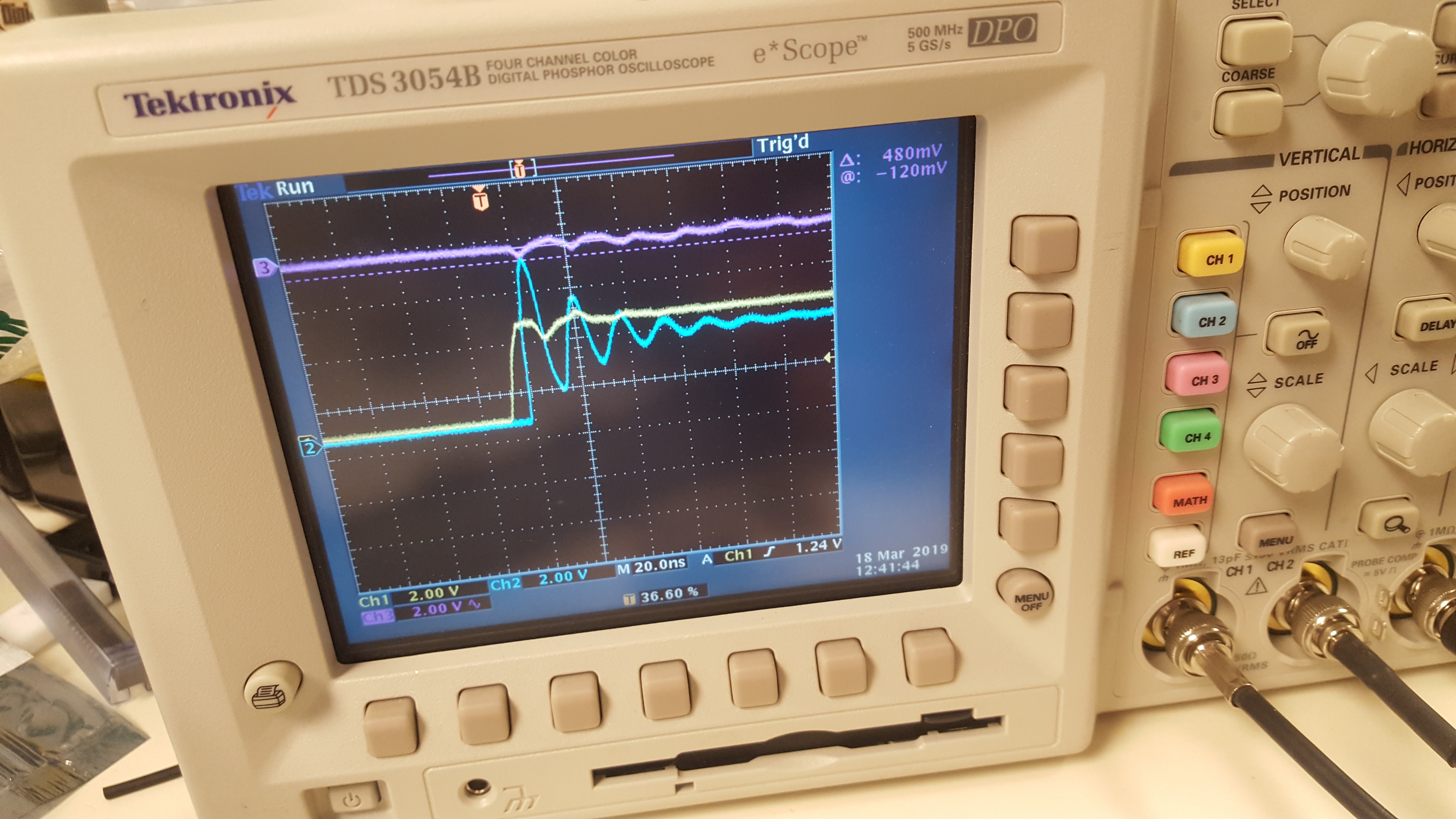
As per the advice of a previous question, I included filtering on a smaller version of this schematic (with only 7 outputs). However, I am still finding quiet a bit of ripple on the output with my oscilloscope, using a 4V pulse generator at 1MHz.

I have tried additional capacitors to filter the power to the individual ICs further, but this doesn't seem to be having an effect. What might be the problem?

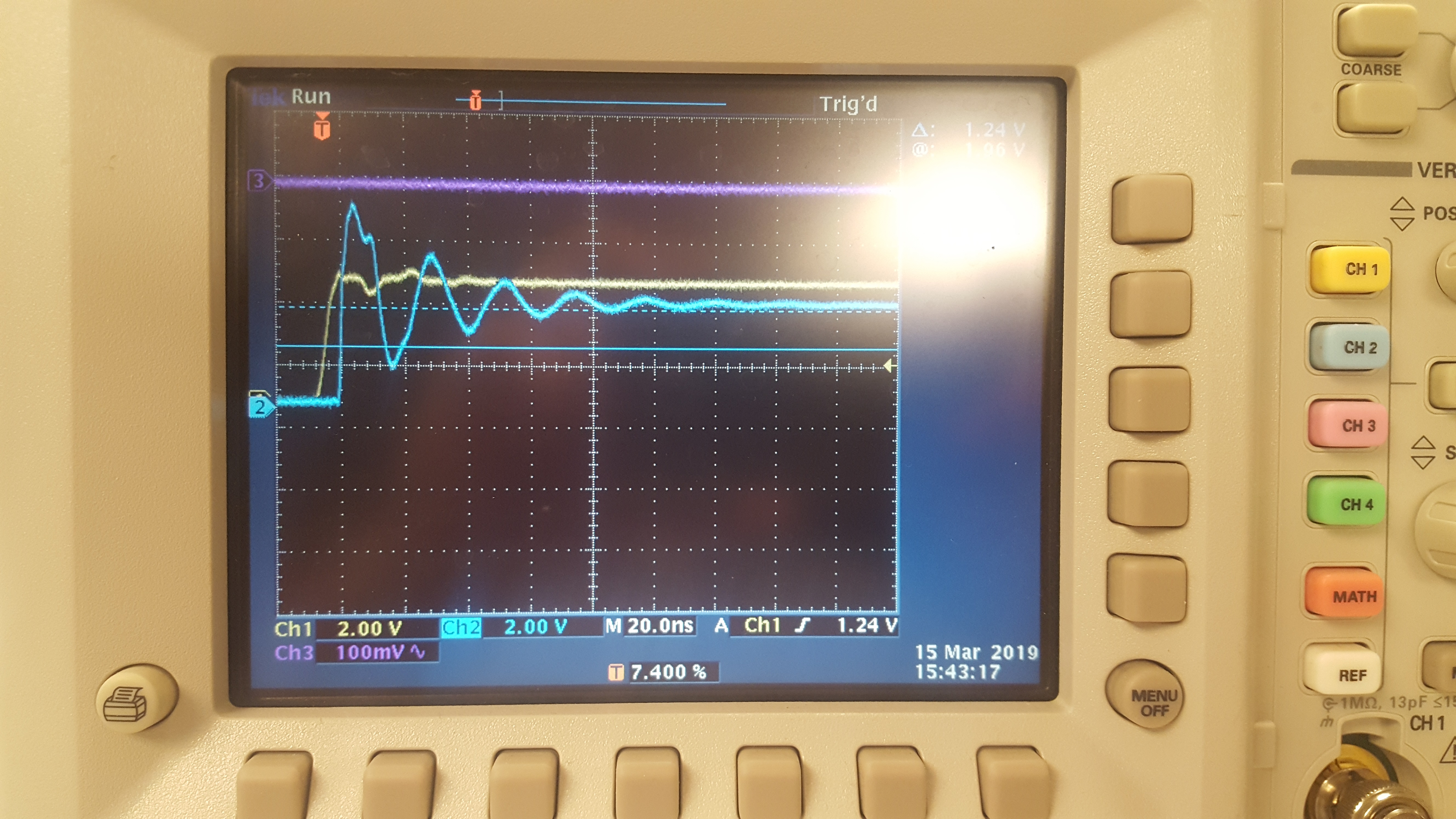
Edit: Here is an additional picture showing the power waveform in purple.

  • Is VCC affected in the same way?
  • VCC shows the same frequency of disturbance, but at a much lower (and acceptable) amplitude.

    I've included an image of the VCC waveform to make things more clear.

  • Hi Jameson,
    It looks to me like you have very strong drivers connected to a light load, aka an underdamped system.

    Checking the schematic confirms this for me - you have two channels of the LVT125 paralleled for each output driver. What kind of load is connected to these devices?
  • A 50 Ohm load is connected.

    Edit: This is incorrect; it looks like my oscilloscope was actually on High-Impedance (1MOhm) mode. Because this is intended to be operated with a 50 Ohm output, I changed this to the intended operating mode and this appears to have solved my problem.

    I will note that your comment solved my problem once I get confirmation from my employer.

    Thank you!

  • That's bitten me a few times as well. Please let me know if I can be of further assistance.
  • Thanks again for all of your help. I'm finding one more issue with my circuit, however, and I was wondering if you guys had any additional insight about this problem.

    Only on channels 19-24, I'm finding the following glitch (in blue) at the beginning of the wave. What could be causing this?

    I should note that these channels are the most distant from both the input and the original LVT125. In addition, I find that this strange behavior only persists when other outputs are also terminated in 50Ohm resistors. Otherwise, the output waveform will be acceptable.

  • Based on your earlier scope shots, I would guess that the input signal is being measured at the input to the system (U14) and the output is being measured at the output of of the system (U11, for example). I wouldn't be surprised to see some ringing on the internal node from U14 to U11, since it's a low impedance output driving a set of high impedance inputs.

    If that's not the case let me know.

    * Edit *

    I should also mention that it might be hard to see that ringing since adding a standard scope probe will increase the line capacitance and could smooth out the signal enough to eliminate the issue.

  • This solved my problem; I just needed a big capacitor across power and ground for U11. Thank you!