This thread has been locked.

If you have a related question, please click the "Ask a related question" button in the top right corner. The newly created question will be automatically linked to this question.

SN74HC163-Q1: Using counter to get lower frewuency

Part Number: SN74HC163-Q1

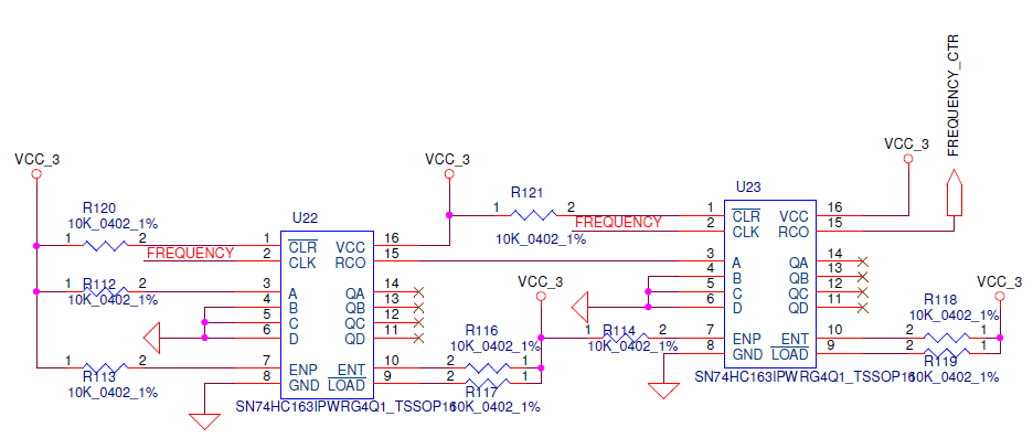
I want get a lower frequency signal from 1MHz with two counters .

as the picture shows.

    that red name CLK signal is 1MHz, the U23 RCO pin is output signal.

If I use two counters as the picture showing,  can I get a   1/256 * 1MHz  signal?

  • Thanks for the post.
    Emrys will respond to you by today on this one.
  • Hello, and welcome to the forums!

    Any standard logic device that uses latches for memory, like this counter, will require a reset at the system startup.  There's some details here:

    And there's a great video that shows how to get a power on reset signal from a simple RC and logic gate combo here:

    Generate a Reset Signal at System Power On

    So, my first recommendation would be to add this power on reset (POR) circuit to the CLR pins of both devices (one circuit will suffice, just use it to reset both at once).

    Next, since you aren't using the load pin at all, you can just tie A B C and D to ground. They won't be used.

    RCO should be connected to the next stage's ENT pin (enable count), as shown on page 11 of the datasheet.  This allows the next stage to count up by just one bit when the first counter 'rolls over' from 1111 to 0000.

    This setup will result in a division by 2 at each output stage, so that means you have 8 divisions by 2, or 1/2^8 = 1/256 of your original signal at QD of the second device.

    I would recommend against using the output at RCO from the second device since the output of that pin will have a skewed duty cycle, but that at QD will be 50%.

    If this answers your question, please click the green "this resolved my issue" button. If not, please respond and I will continue to help.