This thread has been locked.

If you have a related question, please click the "Ask a related question" button in the top right corner. The newly created question will be automatically linked to this question.

SN74HC165-Q1: Logic forum

Part Number: SN74HC165-Q1

Hi Team

We designed SN74HC165-Q1 for fan motor monitoring.

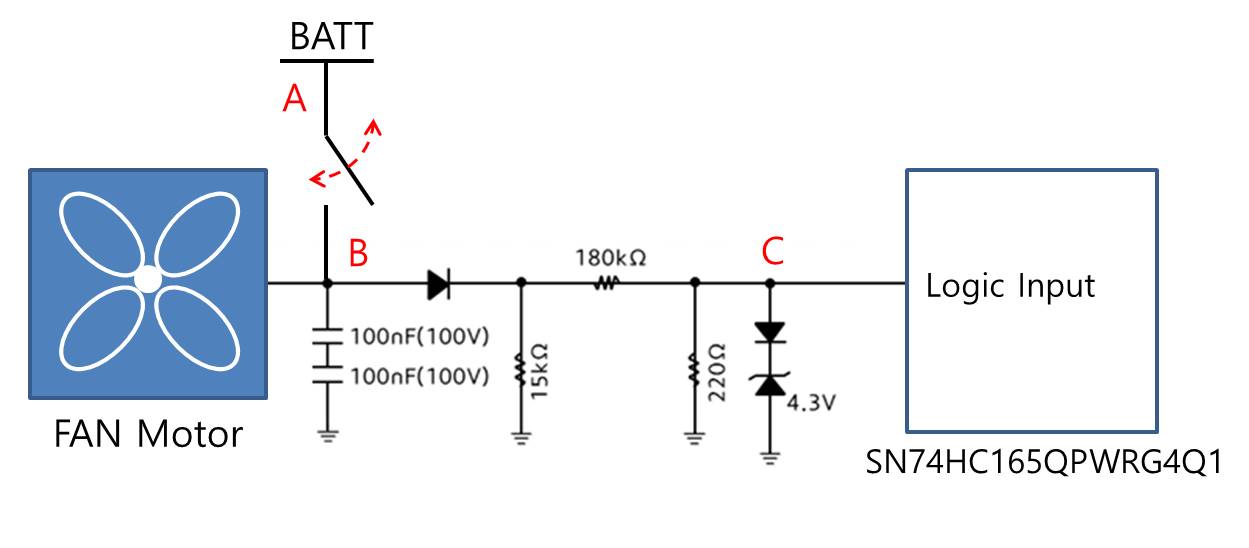
When the switch is turned off, the B-EMF of the motor flows into the logic input pin of the SN74HC165-Q1.

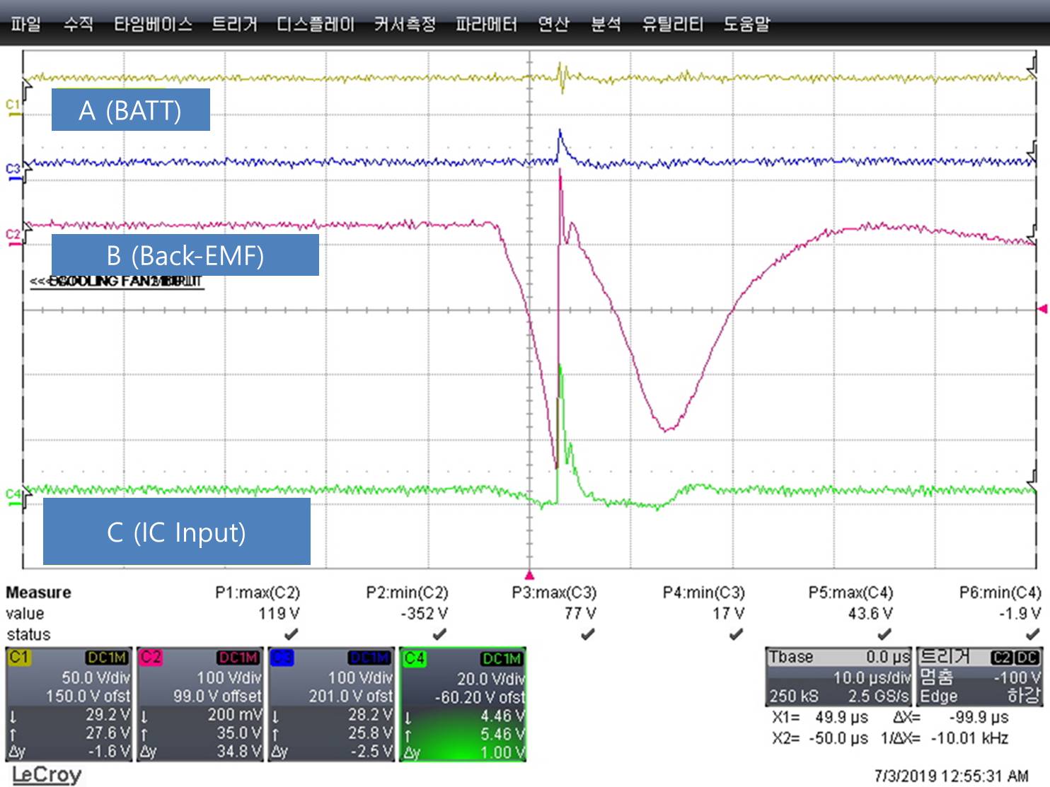
A reverse voltage of about 43V(max) flows for 10us.

Could this reverse voltage cause problems with the IC?

The schematic and measurement waveforms are shown below.

Thank you.

  • There is no negative voltage at point C, but the 3 µs positive spike looks dangerous.

    The absolute maximum ratings require that the current through the protection diode (from the input pin to VCC) must be limited to 20 mA. With a voltage drop of about 40 V over that diode, the current is certain to be exceeded.

    It appears that the diode/Zener combination at point C is not fast enough to clamp the spike. Try adding a fast (Schottky) diode from point C to VCC (and ensure that there is enough decoupling capacitance nearby to eat the energy).

    And/or add a resistor between C and the pin (for example, 40 V / 2.2 kΩ ≈ 18 mA).