This thread has been locked.

If you have a related question, please click the "Ask a related question" button in the top right corner. The newly created question will be automatically linked to this question.

CD4060B: reference design

Part Number: CD4060B

Hi Team,

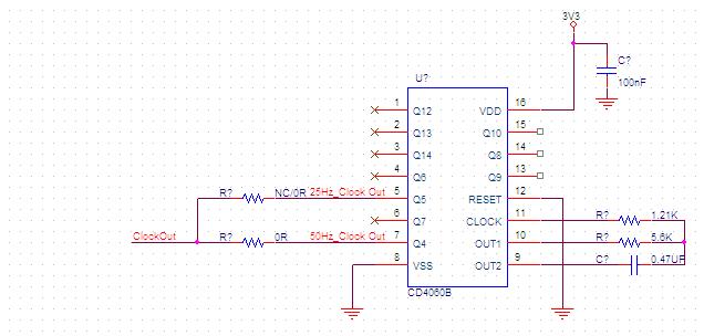
How to use CD4060B to design two 50HZ (or more) simultaneous inputs to two ICs?

Do we have any reference design or circuit?

Thanks and best regards,

Jamie

  • Hi Jamie,

    Can you tell me more about the application?

    * Are you just trying to generate a 50 Hz square wave with no other requirements?

    * Why was this device selected?

    * What is the required operating voltage?

    * What kind of inputs need to be driven?

    * Are there any requirements for the signal (duty cycle, frequency accuracy)?

  • Hi Emrys,

    There are several ICs that need to be synchronized through 50HZ+/- 0.1HZ, so I want to use CD4060B to generate 50HZ output, and then generate multiple sets of 50HZ output to each IC through MM74HC14MTC.

    At present, KHZ's CRYSTAL manufacturers are not making it, and may have to generate 50HZ through resistors and capacitors. (Does your company have recommended resistance & capacitance values)

    Working voltage is 3.3V

    The following is the original description of the IC:

    "An external clock signal to synchronize the MAC cycle of several Domain Master nodes working in the same coaxial channel is required and it must be connected to ZCD pin of each DM’s 88LX5153. This sig-nal must be a square waveform with a frequency of 50 ± 0.1Hz and a period jitter lower than 50μs. This external clock signal must have 3.3V LVCMOS levels. A resistor divider reduces its amplitude to 1.5V in the DCP962 Ref Design as required by the 88LX5153."

    Thanks and best regards,

    Jamie

  • Hi Jamie,

    For 0.1 Hz accuracy at 50 Hz, that allows for a total of 0.1/50 = 0.2 % error.

    Dividing down a signal won't improve the error - ie a signal with 10% error at 1.6 kHz when divided 32 times to get 50 Hz will still have a 10% error.

    I don't know of any way to get that kind of accuracy from an RC oscillator circuit. Even with perfect external components (0% error R and C), the inverter can have variations in threshold value that can significantly impact the oscillating frequency - shifting frequency and duty cycle by 10% or more.

    The only way to really get that kind of accuracy from an RC circuit would be to calibrate every device across temperature at time of manufacturing - adjusting the resistor value to get a precise 50 Hz at the desired operating temperature/voltage.

    In my opinion, a much better way to do this would be to use a microcontroller and crystal oscillator.