This thread has been locked.

If you have a related question, please click the "Ask a related question" button in the top right corner. The newly created question will be automatically linked to this question.

SN74AUP1T14: False Trigger Issues

Part Number: SN74AUP1T14
Other Parts Discussed in Thread: SN74LVC1G14

Hey Team,

We’re seeing something peculiar with a SN74AUP1T14 Schmitt-trigger inverter as used in the following circuit:

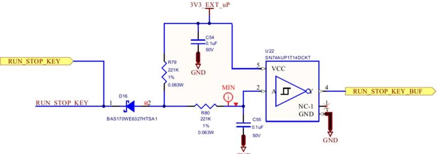
The RUN_STOP_KEY signal on the left goes to a membrane switch in our keypad. The signal is pulled to ground when the key is pressed. The RUN_STOP_KEY_BUF signal on the right goes directly into an i.MX 6UL microprocessor. One of our software engineers noticed that a single keypress was generating two rising edge interrupts. The first interrupt occurred as expected when the key was pressed, but a second occurred after the key was released and the output of the inverter went low. This behavior was also observed when a function generator replaced the mechanical switch; however the problem went away when an SN74LVC1G14 replaced the AUP1T logic device.

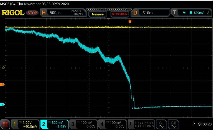
The following oscilloscope images show the output of the inverter by the blue trace and the 3V3_EXT_uP supply voltage by the yellow trace. I was curious to know if the supply was ‘moving’ when the switching occurred. As can be seen the output has an unusual characteristic that I can’t explain.


After changing the horizonal and vertical resolution the signal looks like it could falsely trigger a rising edge interrupt due to the speed at which the microprocessor responds. The i.MX 6UL requires an input transition time of less than 25ns so with a slow transition and noise I believe this is causing the problem.


Do you see any concerns with the way we’re using the part? I thought maybe the time constant on the input was just too long, but speeding it up by removing capacitor C55 didn’t seem to help.


  • Can you capture the input signal?

  • Hey Ramon,

    It looks to me like something is pulling the output down.

    The LVC device has a much stronger output driver than the AUP device, so it sounds to me like whatever is pulling the line down is comparable in strength to the AUP, but weaker than the LVC.

    Is the input pin of the process an I/O pin by any chance? Could it be driving the line low unexpectedly causing bus contention?

  • Emrys,

    Here is a photo showing the input signal (pin 2) in yellow and output signal (pin 4) in blue. Although the input looks like a DC signal it’s just that the time constant is very long relative to the 40us time base of the oscilloscope.

    We would be surprised if the microprocessor input; which is an I/O, is driving the output of the inverter low, but it’s always possible so we will test that theory.

  • Hey Ramon,

    I think you're right - I didn't see originally that the input was transitioning, and it looks like there's some noise imparted to the input, presumably from the internal circuitry of the AUP1T14:

    I've never seen this behavior from a ST input, but the AUP family is relatively unique in how it works -- there's a lot going on in there to reduce power consumption.  It's possible that the slow input combined with the weak driver (220k resistor) results in a feedback loop and internal oscillation.

    Can you get a closer look at the noise on the input?  I'd like to see the frequency, wave shape, and amplitude a little clearer if possible. Also, is that noise with C55 included or removed?  I'd expect the capacitor to significantly dampen noise, so it's odd to see it there.

  • There is noise on the input, and it is apparently larger than the hysteresis. (LVC inputs have a larger hysteresis.)

    The strange output signal is probably caused by oscillations.

    The capacitor at the input should prevent something like this. Can you check if the noise comes through the power supply/GND? Can you show the board layout?