A related question is a question created from another question. When the related question is created, it will be automatically linked to the original question.
If you have a related question, please click the "Ask a related question" button in the top right corner. The newly created question will be automatically linked to this question.
Part Number: CD4047B Other Parts Discussed in Thread: TL494
Dear Sir,
We are looking for CD4047B based 12V DC to 192VAC inverter circuit reference design, so can you please provide a validated reference design for the same.
The CD4047B is a monostable multivibrator - ie a device that produces a single output pulse from an input transition. It is not a DC to AC inverter, in any way shape or form. I have no idea how you would base an inverter on this single component.
It sounds like you're wanting to build an entire power inverter system, so I'm going to notify one of our power teams to comment on this thread. Maybe they can help you out.
Thanks for connecting through E2E. Let me pull together some 12V inverter options I think will help. In the meantime, please feel free to share any other system requirements you have? I will get a response to you by EOD Monday.
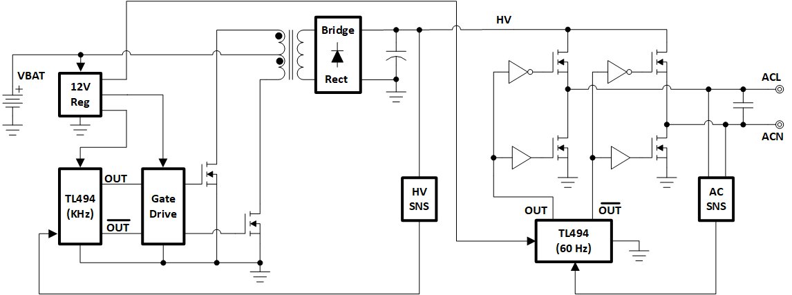
I've sketched below a basic block diagram concept for a modified sine wave convenience inverter. The idea is to switch the transformer at high frequency (hundred's kHz) to maintain smaller transformer size compared to a 60 Hz transformer. Here I am showing one TL494 (complementary output PWM) driving a dual low-side gate driver, used in a push-pull topology. The transformer secondary AC voltage is full-wave rectified into a bulk capacitor where the turns ratio is set for converting VBAT (~12 V) to the high voltage (HV), desired AC peak voltage. The second TL494 is driving an H-bridge at the desired AC frequency (60 Hz). Each leg of the H-bridge is driven by complementary gate driver circuits so that any two diagonal MOSFETs are conducting at any time. AC line (ACL) and AC neutral (ACN) can be sensed in a variety of ways and the duty cycle controlled with the goal of producing a square wave or modified sine wave as shown in the diagram below schematic.
TI does not have a detailed reference design for this concept yet but we are seeing accelerated interest in small size, lower power, low-cost, modified sine wave inverters. Thanks for connecting through E2E and good luck with your inverter design.