This thread has been locked.

If you have a related question, please click the "Ask a related question" button in the top right corner. The newly created question will be automatically linked to this question.

SN74LVC1G123: SN74LVC1G123 output safe state

Part Number: SN74LVC1G123

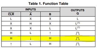
For input /A of this IC,we have to define the default state.In operation we provide 50Hz frequency to /A signal where B and /CLR signal is at high level. We have to do the pull-up or pull-down the signal at /A so that Output Q of this IC is at Low level.On other words we have to define the default state where Q should be at low level.

 Could you please guide us when we pull up /A signal with B and /CLR signal at high level then what is the state at output Q? so basically to insure the output is at low level what should be the state of /A signal I have to set(low or high,need to supply from controller) where B and /CLR signals are at high level -pull ups are present on these two signals.

  • Hello,

    From your description, B and CLR\ are held HIGH permanently.

    In this condition, the output pulse will only be triggered by a falling edge on the A\ input:

    A\ can be held either LOW or HIGH after the falling edge to prevent the output from switching again. A\ can also transition from LOW to HIGH (rising edge) and it will not trigger the output pulse.

    Note that the inputs are passed through an AND gate to trigger the device. The output of this AND gate can be described as follows ( A is the inverse of A\ ):

    Y = A * B * CLR\

    If A\ is LOW (A is HIGH), B is HIGH, and CLR\ is HIGH, then the AND gate output Y is HIGH. A LOW to HIGH transition (rising edge) coming from this AND gate will cause an output pulse. The AND gate output can be held in the HIGH state indefinitely after a trigger without any issues.

    If A\ is held HIGH (A is LOW), then the AND gate output Y will be LOW and the device will not trigger.

    Please let me know if I can be of further assistance.