Part Number: TXS0104E, TXS0108E, LSF0108, LSF0204, LSF0102, LSF0002, LSF0101, TXS0102, TXS0101, TXB0104, TXB0106, TXB0108, TXB0102, TXB0101
Tool/software:
Auto Bi-Directional translators demand additional design considerations over other translators, such as external RC loading to ensure compatibility with host/target devices. These level shifters are weak in drive strength due to passFET architectures (LSF, TXS) or weakly dampened outputs (TXB) to be able to support the auto direction capability. With this in mind, system designers need to be mindful of the output loading requirements. The attached excel document can be used to estimate the expected performance/ characteristics.
7536.Auto_Dir_Translators_Calculator_Tool.xlsx
Please note that this tool should not be used as a standalone tool to evaluate performance of the device. Customers should always verify with silicon per their board specifics to ensure SI is appropriate.
The EVM links below can be used to evaluate the devices:
FAQ: TPLD > Current FAQ
The two biggest causes of slow simulation are:
If the simulation is utilizing a square wave with a period that is much smaller than the total simulation runtime (for example, a 25MHz oscillator has a period that is 25000 times smaller than the default 10ms runtime) the simulation will take an extremely long time to run.
The easiest ways to reduce simulation runtime are to scale down design timings to work with slower clock speeds and/or to reduce the End Time setting under Simulation.
FAQ: TPLD > Current FAQ
Numerous TPLD products are either pin to pin or layout compatible with competing products. Our products utilize standard, JEDEC packaging standards.
FAQ: TPLD > Current FAQ
Once a TPLD is permanently programmed or “burned” through OTP, the design cannot be changed. If you wish to change your design after permanently programming an OTP part, a new, previously unprogrammed part must be used.
FAQ: TPLD > Current FAQ
TPLD is programmed through SPI communication enabled by the programmer firmware and InterConnect Studio (ICS). Each TPLD device uses 5 pins to program the device: 4 pins for SPI communication and 1 pin (GPI) that provides a specific input sequence to act as a programming unlock and then provides a high voltage (8V) to the device to permanently program it.
FAQ: TPLD > Current FAQ
TPLD is programmed through our software tool, InterConnect Studio (ICS), in combination with a TPLD programmer and EVM. TPLD programmers and EVMs can be found on the “Hardware development” section of any TPLD product page, such as here for the TPLD1201: TPLD1201 data sheet, product information and support | TI.com
For more information on how to use ICS, please refer to the ICS User’s Guide: Interconnect Studio User's Guide
FAQ: TPLD > Current FAQ
No, current devices do not support in-system or inline programming (support is planned for future devices). For large scale production, we recommend you have TI program the devices before shipping. Customers can program devices themselves during production using a TPLD programmer and corresponding EVM.
FAQ: TPLD > Current FAQ
Yes. Currently TI has enabled Dediprog to work as a third party for programming TPLD.
FAQ: TPLD > Current FAQ
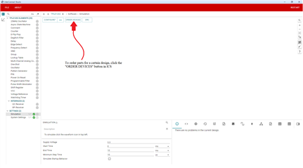
Customers can order devices for production through InterConnect Studio (ICS). TI can program devices (at no additional cost!) before shipping with the submitted design if the order quantity is one reel or more (3000 units).
Customers are responsible for verifying that their design is correct, and for submitting the correct design when ordering.
TI will test for device functionality and will read back the CRC code to ensure the correct bitstream was programmed, but will not test customer designs.
FAQ: TPLD > Current FAQ
TPLD uses Floating-Gate One-Time Programmable (OTP) technology to program its parts, as opposed to other Non-Volatile Memory techniques such as eFuses or AntiFuses, or Volatile Memory technologies such as EEPROM or RAM.
Floating-Gate OTP technology works by trapping charge on a floating gate to store a binary digit and program the device. This process requires high voltages (8V for current TPLD devices) and is irreversible; once a TPLD device is permanently programmed or “burned” using this process, it cannot be reconfigured.
TPLD does not have any volatile memory, but utilizes registers to store and load device configurations before the device is permanently programmed.
