This thread has been locked.

If you have a related question, please click the "Ask a related question" button in the top right corner. The newly created question will be automatically linked to this question.

SN74VMEH22501A: STILL PROBLEM PERSISTS DURING BURST

Part Number: SN74VMEH22501A
Other Parts Discussed in Thread: SN74LVC245A, SN74LVC244A,

Hello Andrea again writing,

just to inform you that issue is not yet resolved.

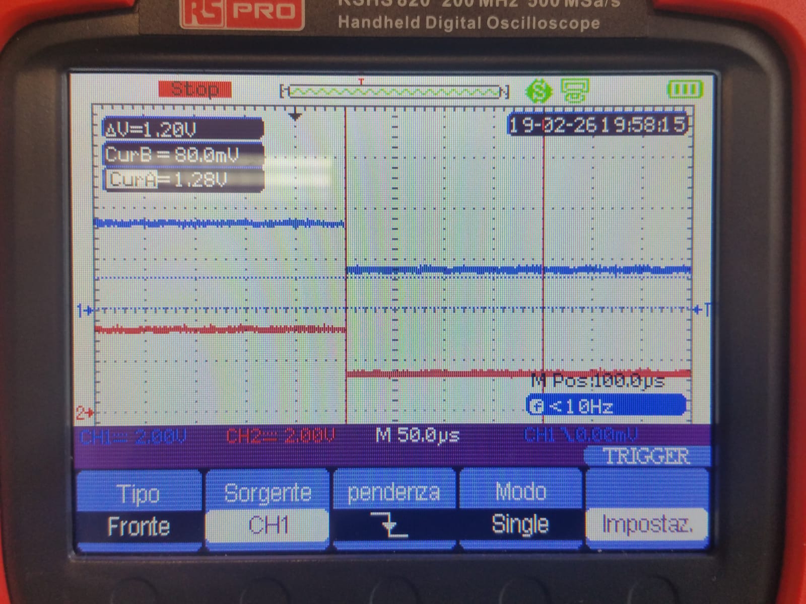
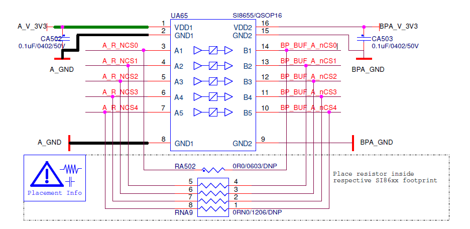
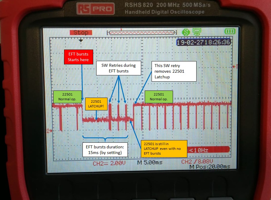
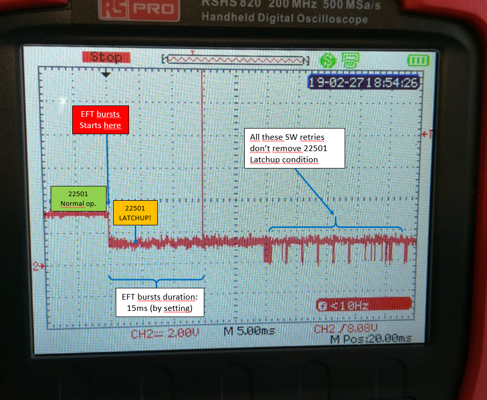
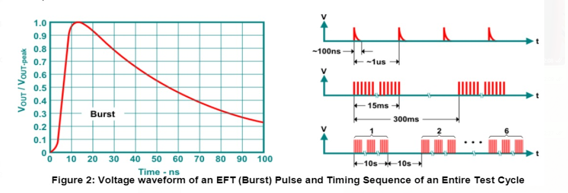
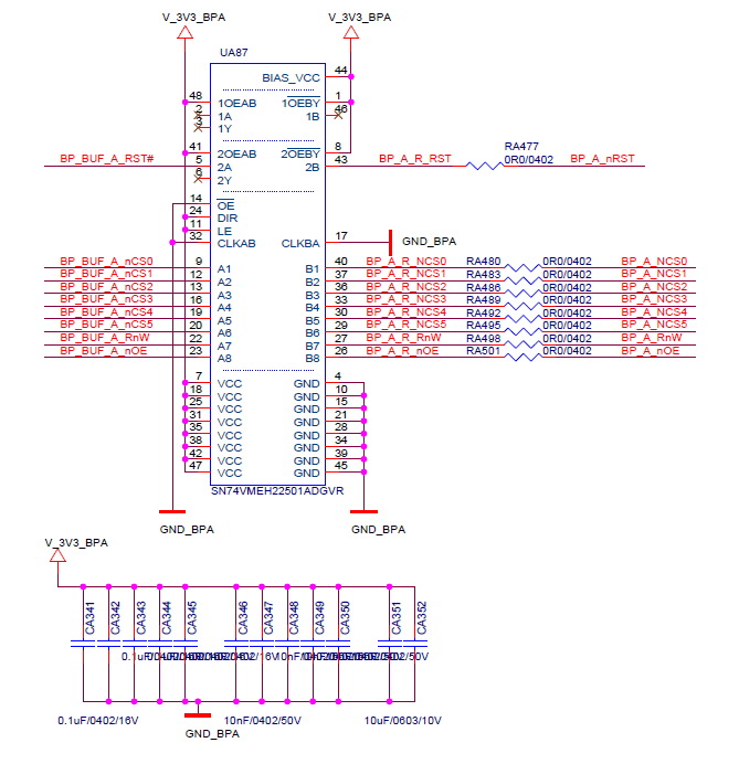
Given the circuit below, i move signals BP_BUF_A_nCSx from an FPGA. The output on the left side has issue when i apply a EFT burst

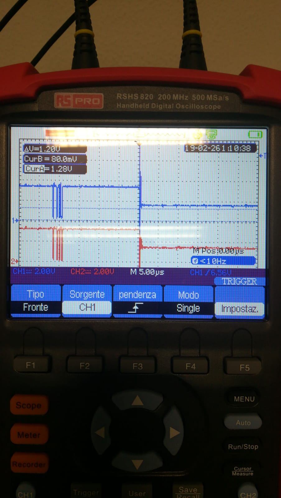
Find attached the waveform taken on the output signals *CS and *RnW: after the burst the signal is steady at 1.5V, instead of 3.3V.

Please an urgent feedback is required; possibly an italian field application engineer is appreciated.

Many thanks

Andrea

  • Andrea,

    on the schematic, I would recommend having a gnd on the 1A and 1B pins.
    Do you have details on the scope settings? Hi-Z or 50ohm? what is the cap loading?

    Any scopeshot available for Vcca / Vccb?

    It will be helpful for review and someone from our team will get back to you on this.

    It also seems that you only need a buffer device and not seem to be using the DIR/ LE/ CLK pins. 

    you could consider using buffer or transceiver we have in our portfolio like the SN74LVC245A / SN74LVC244A 

  • hI ShreyasRao,

    many thanks for feedback

    Scope setting is Hi-Z, at the moment i dont have information about cap loading, i will check.

    Ok i will provide Vcca/Vccb scopeshot

    Yes actually we use 22501 only as a buffer; we chose it because we thought they could be more reliable in harsh environment:

    the application is for railway and we have to withstand electrical noise.

    We have to pass pre compliancy tests injecting EFT bursts and surges, and prove that our protections are working good.

    The EFT bursts are not directly injected on the signals under analysis, but on field signals that are galvanically insulated from the 22501 signals.

    How ever it is possible that the injected noise is propagated in air towards the neighbor components 

    We will stuck 1A and 1B pin with a patch, and we'll repeat the test and come to you very soon with more information.

    Just as an additipnal information:

    when the signal is at 1.5V (after the EFT burst), the buffer heat up! it seems like the buffer has an internal clash

    bye for the moment

    Andrea

  • Hello Shreyas

    we have stucked 1A, 1B to '0', as requested.

    Result did not change: after the burst (two peaks as shown in the picture below) the buffer output goes to 1.5V and there is no way to change this situation, unless a power OFF/ON sequence

    Wait for comments

    Andrea

  • Hi Andrea,

    Can you confirm which color signal correlates to the input and output? It seems like the input is being held at 1.5 V. The 3A port inputs have have bus hold circuits which don't work well with pull-ups/pull-downs. Can you confirm as well if the inputs have these? I'm trying to get a little visibility to everything connecting to our device. The device will not like having the inputs close to half VCC which is why it gets hot. This leads me to believe the issue is at the input.
  • Hello,

    both red and blue signals refer to two different outputs (CS0 and RnW), pin 40 and 27 of the same buffer.

    The transition 3.3V to 1.5V happens when a EFT burst is applied

    We dont have pullups at the input, but the signals going to the 22501 come from a bus coupler by silicon labs, in order to have galvanic insulation between the host cpu and the backplane domain.

    See below schematic.

    now we'll try removing the bus coupler and mounting the bypass resistors. Thus the 22501 input is driven directly by the FPGA

    The guess is: currently the bus coupler is not able to provide enough current to the 22501 inputs,and it causes it to latch up and heat during EFT bursts

    The FPGA driver should be able to provide more current

    What's your opinion?

    Any suggestion?

  • **update**

    i hope to be as clear as possible

    these are the measuring different scenarios

    1) no scope probe connected at buffer inputs nor at outputs:

    EFT Burst is applied

    Results:

    Test by SW fails. Measuring with the scope *after* the EFT burst (i.e.: "as if" in normal operation) we see 3.3V at input and 1.5V at output

    2) scope probe connected at buffer outputs:

    EFT Burst is applied

    Results:

    we see at the scope the transition 3.3 to 1.5 during the EFT bursts  (i.e.: the images we sent you)

    Measure at input after the EFT bursts reports 3.3V

    3) scope probe connected at buffer inputs:

    EFT Burst is applied

    Results:

    we see at the scope the transition 3.3 to 1.5 during the EFT bursts also at inputs!!

    Measure at output after the EFT bursts reports 3.3V

    I hope it helps you to make it clearer.

    Andrea

  • ***more update***

    Actions done: 

    Removed SILABS Bus couplers; now 22501 is driven by the FPGA

    Please see the two scopeshot below.

    The two waveforms reports the 22501 output in two separate test (identical tests) . No probes at the input.

    Enlarged timescale from 50us (previous images) to 5ms.

    SCENARIO 1

    The 22501 is working bad during the EFT bursts; but the 22501 is able to force a "0" and a "1" - after EFT burst ends the 22501 works good.

    SCENARIO 2

    In this case unforntunately, by chance the SW is doing nothing during EFT; after the EFT we see the SW retries, but in this scenario the 22501 is only able to force a "0", not a "1"

  • for your interest, below the specification for the EFT bursts

    A.

  • Hi Andrea,

    Thanks for the detailed report of you debug steps. I have a better understanding of the things connected to our device. My concern now is with the actual EFT bursts. What voltage is being applied during the burst? Based on a quick skim through the specifications it seems like we are talking about a few kV here? Does this test conform to the JESD 78, Class II specifications?
  • Hello Dylan

    we are applying a 2.250kV burst (the level established by the standard should be 2kV), The description of the duration of the burst sequences is provided in the previous picture.

    A.

  • Standard used tof the EFT test is EN61000-4-4 (capacitive clamp on I/O).
    Please notice that the capacitive clamp involves I/O signals that are not directly connected to the buffer. There are at least two galvanic insulations from I/O to buffer.

    So most likely the noise is propagated in the air
  • Hello

    Just in case i was not clear enough, i do confirm that the issue we are experiencing is blocking for a production.

    An urgent feedback is required

    Thank you

    Andrea

  • Hi Andrea,

    From what I've gathered this EFT test violates the specs for our device. I can't guarantee proper operation of the device when operating outside of spec.
  • Dear Mr Hubbard

    i am sure that Texas Instruments can make an extra effort to provide a more satisfactory answer to a customer having an issue.

    Anyway we have solved the issue by ourselves.

    Many thanks the same

    Andrea

  • Hi Andrea,

    I apologize if my answer was unsatisfactory, but not being an expert on EFT bursts I'm not sure the leniency of the spec. We established that the burst was over the rated voltage of the part which is most likely the reason we see latch up. I would suggest to lower this voltage and run the tests again to see if the problem persists.

    May I ask how the problem was fixed to help others who may also be performing similar EFT testing?
  • Hello

    why is it not possible to escalate the issue to an EFT expert by TI?

    The burst test we are performing is a standard testing procedure for railways application, so reducing the amplitude of the test ic totally out of discussion

    best regards

    A.


  • Hi Andrea,
    I spoke with TI's ESD and Surge Protection protection expert regarding this issue. The majority of TI parts are not rated for EFT protection, including the SN74VMEH22501A. The datasheet makes no claim that the device is IEC61000-4-4 or EN61000-4-4 compliant.

    In order to get protection for EFT, an IEC61000-4-4 rated ESD protection device can be used external to the device. Almost all of TI's ESD devices cover for the highest level of EFT.