This thread has been locked.

If you have a related question, please click the "Ask a related question" button in the top right corner. The newly created question will be automatically linked to this question.

SN74V293: Unexpected offset value

Part Number: SN74V293

I have a number of prototype boards that incorporate 'V293 FIFOs.  During configuration, firmware verifies the operation of components on the assembly, including the FIFOs.

The previous version of the prototype (using 'V293s with part marking 74COS9TG4) operates correctly, and returns the expected empty and full offset register values.  In this application, both offset values are set to 16383 using pin straps.

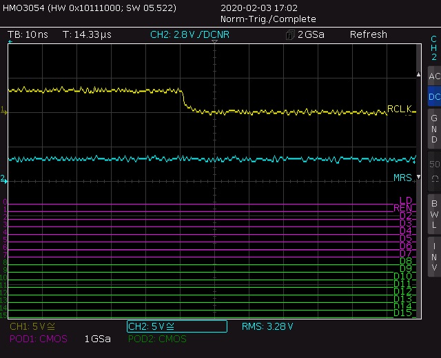
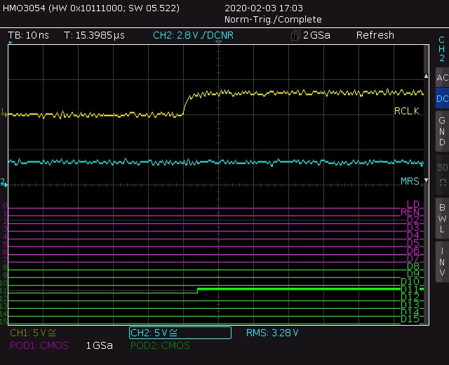
The latest version of the prototype, populated with devices that have a part marking of 84AZVETG4, returns different values for the two offsets: the empty offset is incorrect (and its value varies from one run to another), but the full offset is always the correct value.

Are there any known issues with specific batches of these devices?

  • Hi Colin,

    Have you tried using one of the V293 that had the correct offset outputs on the prototype board that had the different offset outputs? This way we can guarantee there is something different happening on the parts with 84AZVETG4 markings.

    Thanks!

    -Karan

  • Hi Karan,

    Thanks for the response.

    Unfortunately I have neither the tools nor the dexterity to non-destructively remove a 'V293 from the old prototype and then fit it to the new one!  And I don't have any spares from the earlier build, either.

    In the meantime, however, I have ordered a couple of different grades of 'V293, which I'll try out.

    It sounds as though this isn't an issue that has previously been noted.

    Regards,

    Colin

  • Hi Colin,

    Let me know how these new parts go. No other customer has reported the issue you are mentioning about. The datasheet mentions the default offset values are set during master reset by the state of FSEL0, FSEL1, and LD. Are you sure the voltages on these pins is correct? What is the offset value you are seeing?

    The offset registers can be programmed (and reprogrammed) any time after master reset, regardless of whetherserial or parallel programming has been selected. Are you sure that the offset registers are not accidentally being reprogrammed?

    Thanks!

    -Karan

  • Hi Karan,

    I'll fit the new parts later this week, and let you know what I find.

    However, I've been using these FIFOs on prototype boards for the last couple of years (this is a project that's dragged on a bit...).  The empty and full offset values have been configured the same way (using the master reset and pin levels) all that time.  The device gets reset and reconfigured frequently while the unit is running.

    I'm detecting the problem because, each time the device is reset and reconfigured, the reconfiguration and FIFO operation is verified (an exhaustive test only takes a few milli-seconds).  On the new boards the readback of the empty offset value fails.  The new boards are a batch of 10 that have been manufactured by a board assembler, and would have been the first production units had they passed self test.

    Any user that doesn't perform the check on these register values wouldn't see the fault.  In many cases (including my own), the error wouldn't be apparent if the verification weren't undertaken.  In my application, only the full offset is used (only the PAF pin is monitored).  So the fault may be present on other devices, but would only be seen by customers using the empty offset or testing its configuration value.  Even then, the erroneous value of the empty offset register might not be apparent.  I'm seeing the empty offset value vary across different reconfiguration and test cycles, but 22286 instead of 16384 is very common.  That might not affect operation in many applications.

    Regards,

    Colin

  • Hi Colin,

    It is difficult to say what is causing this error. I recommend you try the new parts in both your old and your new boards to see if you get the same error.

    This is the first time I am seeing a report of an incorrect return on the empty offset register. I would check and confirm that the way you are reading your offset registers is correct and there is no error happening in setting the offset registers with the 3 pins.

    Thanks!

    -Karan

  • Hi Karan,

    I've tried new parts in two new boards, and the empty offset register still reads back incorrectly.  As I've noted previously I can't swap these parts out non-destructively; at £40 per component, it's not something I want to do too often.

    I have 10 assemblies from my board supplier.  The boards incorporate diagnostics, so this issue caused numerous failures.  After swapping out FIFOs (sometimes repeatedly), the supplier was able to get the test to pass.  Of these 10 assemblies, one is currently out of action due to other development work, 7 work fine, and two are still showing this issue.  Given that all the previous prototypes and seven of the new prototypes are functioning as expected, it seems unlikely that the method used to read back the offset registers isn't correct.

    I've also performed more tests, and can confirm that it's only the read back of the empty offset register that is incorrect.  Specifically:

    • After setting the offset registers using the three pins, I've read back the offset registers multiple times in sequence (as described in the parallel programming mode section).  The empty offset register value is consistent, but wrong; the full offset register is correct.
    • After setting the offset registers using dedicated write cycles, the offset register values both read back correctly.
    • I've added a function to test the offsets by filling and then emptying the FIFO.  Even when read back of the empty offset register returns an incorrect value, the test shows that the offset is correct.  So I can be confident that the 3 pin configuration is correct.

    This is a difficult debugging issue.  Pragmatically, the devices function correctly as FIFOs, and I have a workaround (parallel program the offset registers).  But that seems unsatisfactory.  I've been working on this design for a couple of years without FIFO issues, using register readback to confirm that the offset registers have been correctly set during master reset.  That's stopped working consistently.  It would be very helpful to discover why the situation has changed.

    Regards,

    Colin

  • Hi Colin,

    Can I get a schematic of the part? Can I also get scope shots? I would prefer to see input and output waveforms of the full read happening at the pins of the device. Besides the offset values, is the FIFO functioning properly? I have a feeling that the bits are getting corrupted due to slow edge rates or some form of incorrect transmission. There should be reason for the IC's to stop working.

    Thanks!

    -Karan

  • Hi Karan,

    The schematic runs to 11 sheets; I'll just include the three that are relevant to the FIFO (with borders and identifying marks removed):

    U8 is an STM32F427 controlling the system.  U14 is the FIFO.  The PCB is 4 layer; in the area where the FIFO is located there's a solid 3.3V plane and a solid 0V plane, and each of the power pins of the FIFO is decoupled with a 100nF ceramic in parallel with a 10uF ceramic.  The supply should be very stiff.

    For the trace captures you've requested, I've tied SEL0 directly to 0V and SEL1 to 3.3V through a 10k resistor so there are fewer signal lines to verify.

    The scope is a MSO, with 16 logic channels and 2 analogue channels.  To make best use of the channels, D0 and D1 have been allocated to LD and REN, respectively, although LD doesn't change for the duration of the configuration and readback.  All channels are named on the scope traces; RCLK and MRS are connected to the analogue channels so you can see rise and fall times. Correction: the lines labelled D2:D15 should be labelled Q2:Q15.

    This is the whole master reset configuration, followed by read back of the empty and full offset registers (8 reads, but the readout just repeats four times):

    This is a closer look at the first two reads:

    You can clearly see that the empty offset is 2048 (assuming D1 and D0 are zero; whatever they are, the value isn't the 16383 expected), and the full offset is 16383 (assuming D0 and D1 are one, which the code tells me they are).

    The following four screen captures are "close-ups" of the falling and rising edges of MRS and RCLK:

    You asked "Besides the offset values, is the FIFO functioning properly?"  The only incorrect operation is the read back of the offset registers.  As I mentioned in a previous post, I've added an exhaustive test that fills and then empties the FIFO and can confirm that, even though the empty offset register read back indicates the wrong value (it isn't always 2048, sometimes it takes other values), the empty flag is active when there are 16383 values left in the FIFO.

    Regards,

    Colin

  • Hi Karan,

    I've managed to remove one of the 'V293 parts from the earlier prototypes (that always read back the correct offset values), and pasted it onto one of the new prototype boards (which reads back incorrect offset values).  Correct operation followed the 'V293, not the assembly.  So, the old (correctly working) prototype FIFO (batch code 74COS91T) worked on the old prototype, and still works on the new prototype.

    In place of the 'V293 I removed, I put a new (straight from the reel) 'V293 on the old prototype.  It started reading back incorrect offset values.  Th new 'V293s have batch code 84AZVET.

    I presume that all the different grades (-6, -7, -EP) are selected from the same wafers.  In addition to the -EP parts, I bought a couple of -6 parts (which I've also used on earlier prototypes when the -EPs were out of stock).  I've fitted one of them and it, too, reads back incorrect offset values.

    Have there been any mask or process changes to this family of parts recently?

    Regards,

    Colin

  • Hi Colin,

    There aren't any process changes happening with these parts. If changes are made, PCN will be issued for the part.

    They parts may be from different fabs which may be a reason. Can you provide me with the shipping label from the batches that don't work and the batches that do? I will forward that to quality to find out.

    Thanks!

    -Karan

  • Hi Karan,

    I've finally got to the bottom of what's happening, and I can create the problem repeatably on all devices.

    It looks like there's a minor bug in the operation of the FIFO.  It won't be apparent in many (probably most applications), but it's caught me out on this occasion.

    If a parallel configuration of offset values occurs prior to a master reset, the value of the empty offset register read back by any subsequent parallel read back is the value set by the parallel configuration, NOT the actual value as configured during the master reset.

    The master reset cycle is correctly reconfiguring everything EXCEPT the read back value of the empty offset register.  Which is very unexpected (not least because the actual empty offset value used by the device IS correct).

    Only the empty offset register is affected by this bug: if both the empty and full offset registers are parallel programmed prior to the master reset, the full offset register value is always read back correctly.

    Once the empty offset register has been configured using a parallel load cycle, master reset cycle empty offset register configuration values are never correctly returned.

    Because I don't have pull-ups or pull-downs on the control lines from the processor to the FIFO, there's a short period where the lines are high impedance.  On some of the boards bus activity appears to be causing some spurious writes.  I wasn't worried about this because I execute a master reset, and had reasonably assumed that that would then configure the device correctly.

    The workarounds for this are all obvious, although it would be nice to see an erratum on the website or, better still, a part re-spin to eliminate the anomaly.

    Regards,

    Colin

  • Hi Colin,

    I am glad you were able to get to the bottom of this problem and solve it.

    I have made a note of this mistake and I will get this tested and reported.

    I know you were only having this issue occur with new parts you purchased and not the older ones you had on your original board. Is this still correct?

    Is this an error occurring for you only on the newer parts you have purchased?

    Thanks!

    -Karan

  • Hi Karan,

    This problem occurs with ALL 'V293 parts I have.  On the earlier boards the combination of pin allocations and board layout doesn't appear to have been causing spurious writes to occur during initial system configuration, but with the code I've written to investigate the problem it is repeatable on all assemblies with all parts.

    Regards,

    Colin

  • Hi Colin,

    Thanks for reporting this. I will go ahead and add this behavior to be tested.

    Thanks!

    -Karan