Other Parts Discussed in Thread: SN74LVC1G125, SN74LVC1G17, SN74LVC1G32, SN74LVC1G08, SN74LVC1G02, SN74LVC1G00, SN74LVC1G14, SN74LVC1G04, TINA-TI, SN74HC125, SN74LVC1G18, SN74LVC1G66, SN74LVC1G79, SN74LVC1G175, SN74LVC1G373, SN74LVC1G374, SN74LVC1G3157


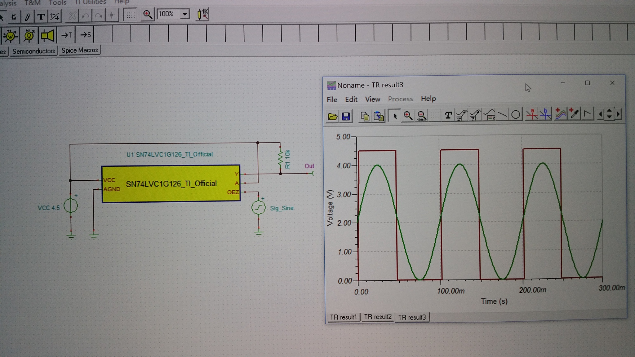
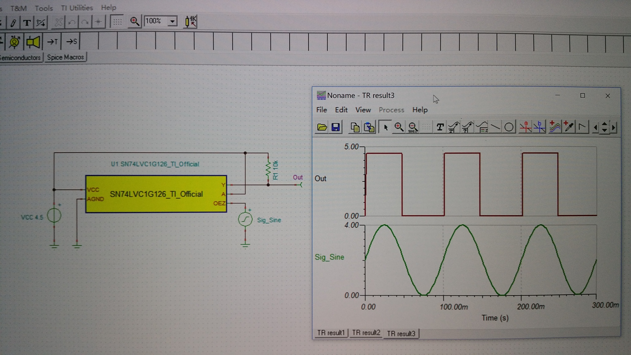
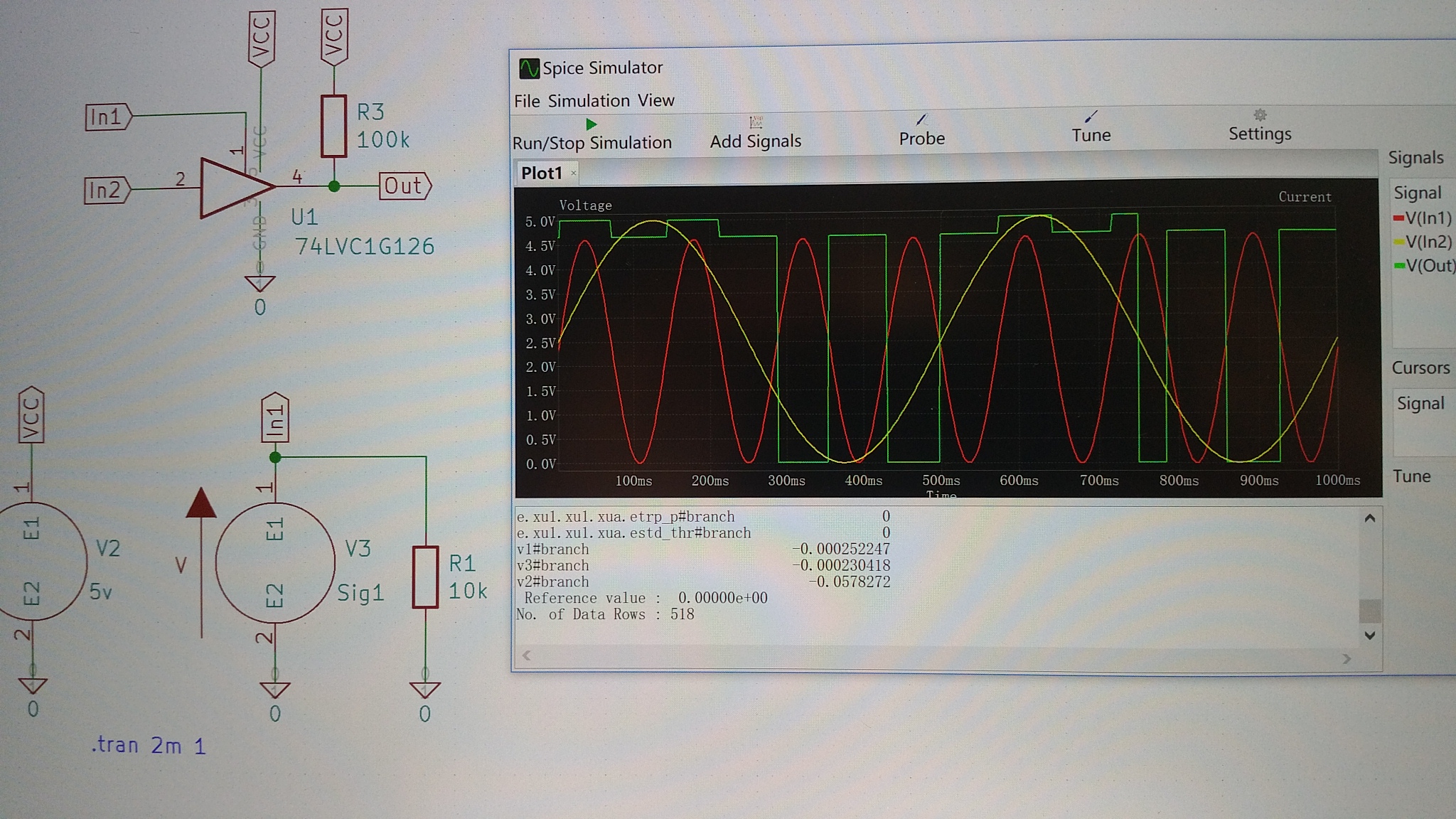
Problem: The simulation results of thi-state gate are not correct, the result about high resistance state are same with an AND gate.
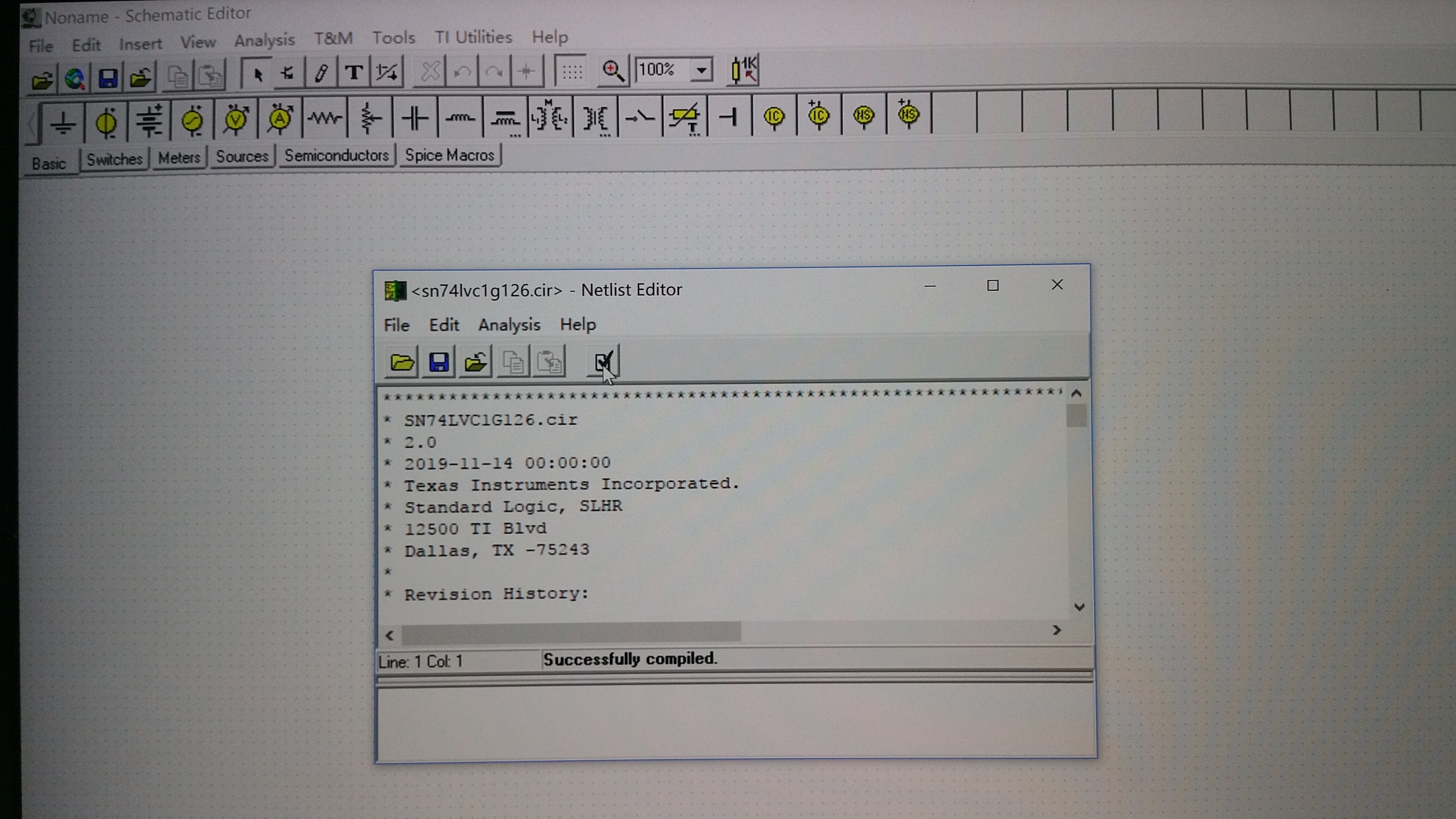
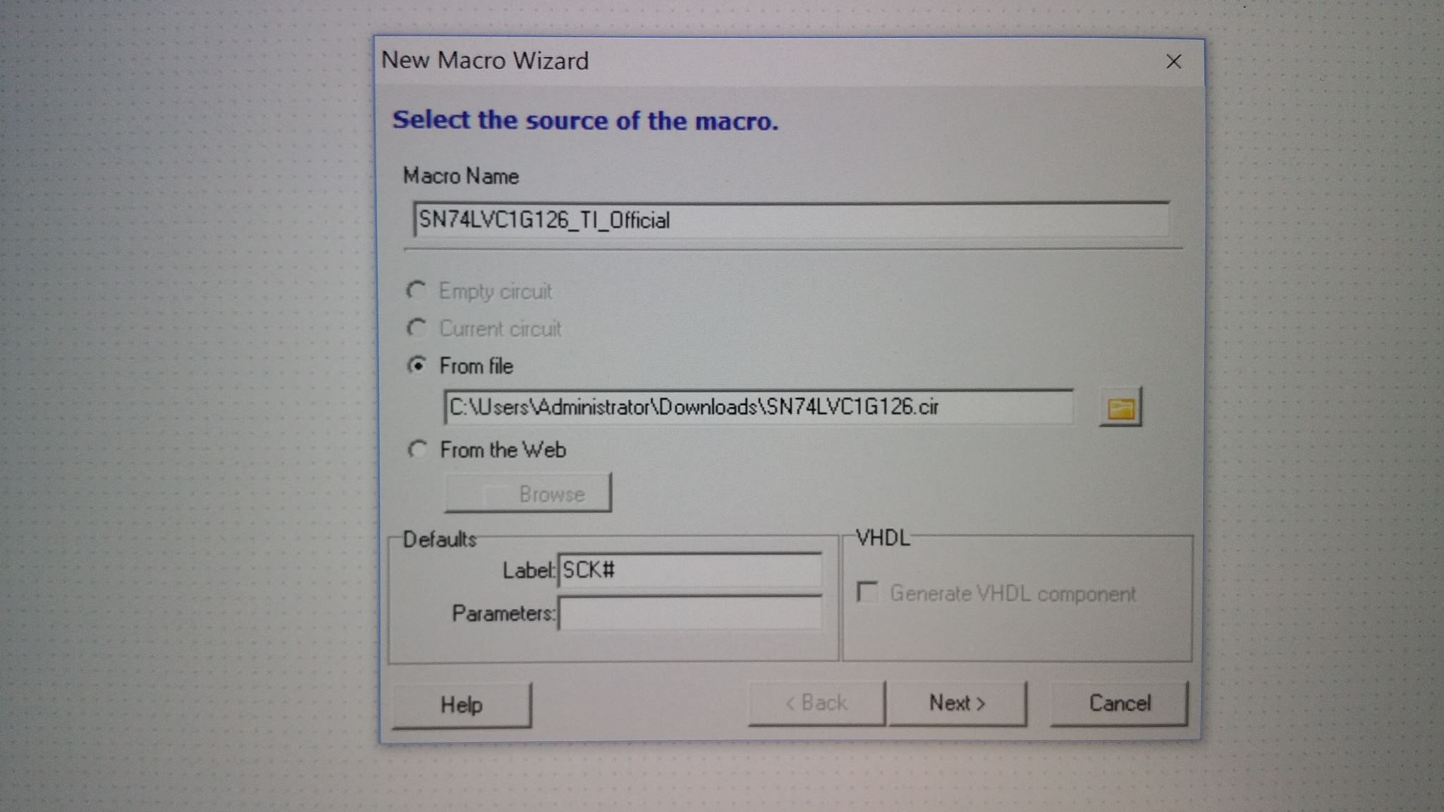
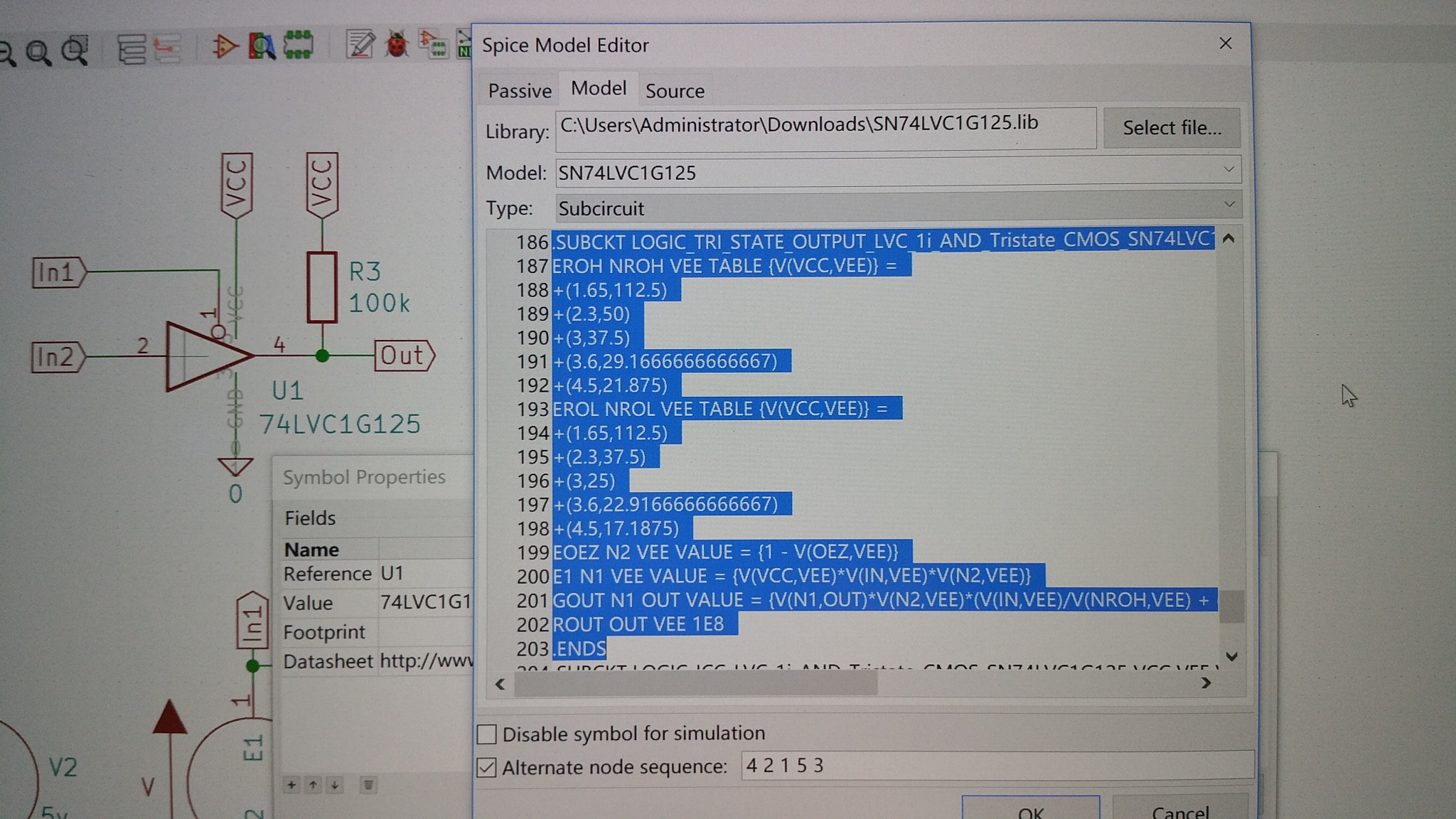
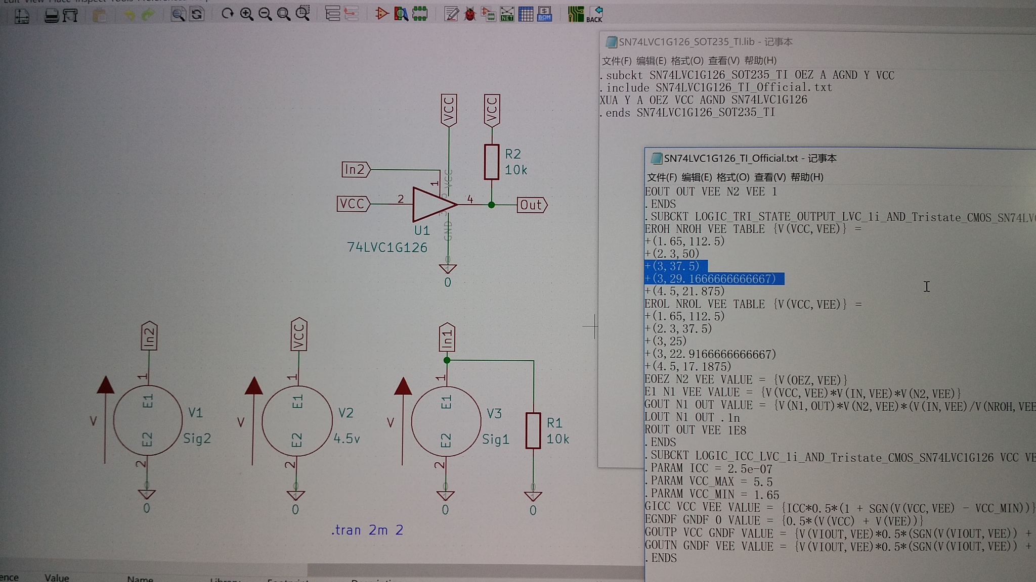
In testing, Kicad and Ngspice are used as simulation platform, and the SPICE model of sn74lvc1g126 is downloaded from Ti Official Web and then renamed as sn74lvc1g126_TI_Official.txt. The sn74lvc1g126_SOT235_TI.lib, which is used for the thi-state gate model, is obtained by reordering pin's sequence.
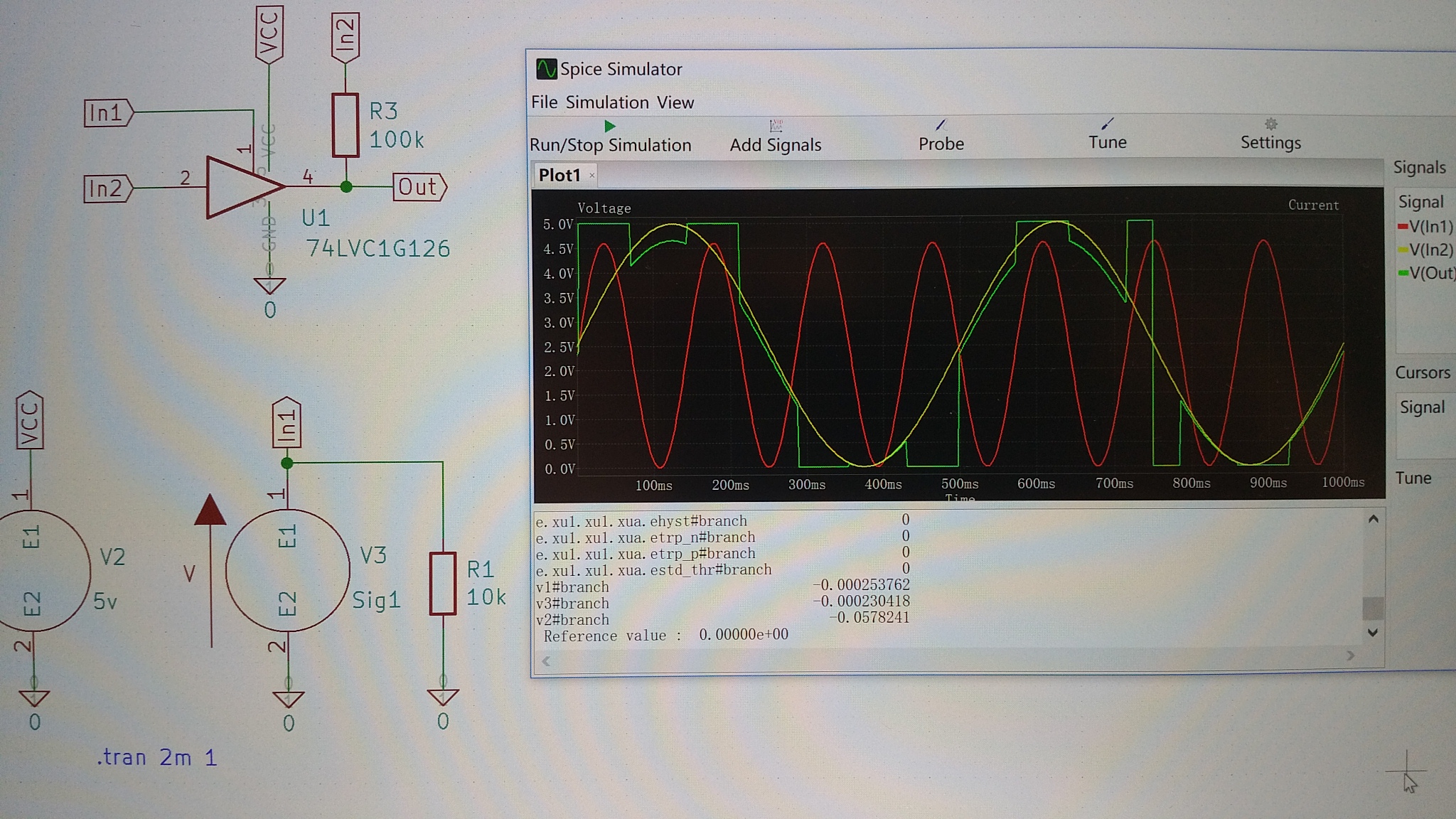
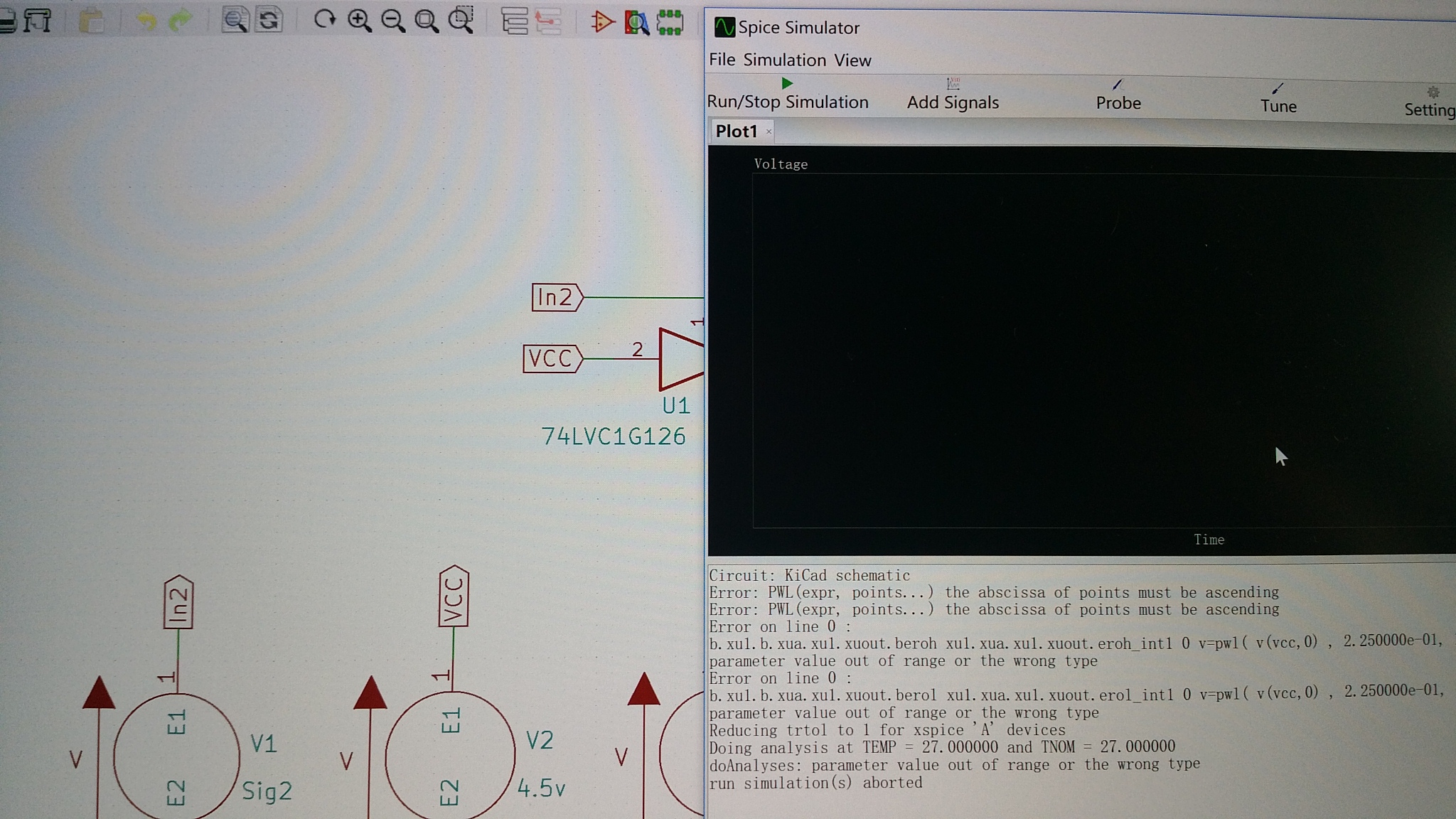
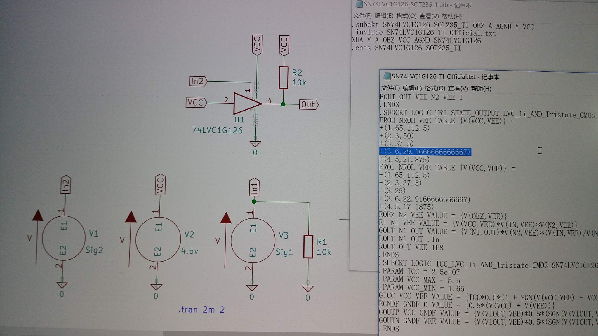
I set the part symbol according to Fig 1. The error message is shown in Fig 2 when I run the simulator for the first time. I checked the official spice file and found that there seems to be a problem in two places, as shown in Fig 3. Then I tried to modify the data, change 3 to 3.6, as shown in Fig 4, and then ran the simulator to get the result as shown in Fig 5. However, this result is not correct. This is the result of AND gate, not result of high resistance state, which should be a horizontal line with a value of 4.5V.
The same problem also appeared in the simulation experiment for sn74lvc1g125 with official spice file. I don't know where the problem is. I guess there may be three possibilities:
1. There may be some errors in the TI official spice file.
2. There are some compatibility problems among the TI official spice files, KiCad and Ngspice.
3. I didn't use the simulation platform and official spice file in correct way. However, the TI official spice files such as sn74lvc1g00, sn74lvc1g02, sn74lvc1g04, sn74lvc1g08, sn74lvc1g14, sn74lvc1g17, sn74lvc1g32 were tested by the same method, and the correct results were obtained.
So, I want to know where is the simulation problem of sn74lvc1g126 or sn74lvc1g125 and hope to get your help, Thank you!