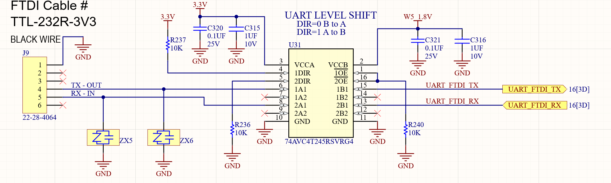
We are using this chip for voltage translate between 3.3V and 1.8V. The 1.8V side is not going to ground. What would be the likely cause of this?

-
Ask a related question
What is a related question?A related question is a question created from another question. When the related question is created, it will be automatically linked to the original question.