This thread has been locked.

If you have a related question, please click the "Ask a related question" button in the top right corner. The newly created question will be automatically linked to this question.

TXS0206A: SD card connection on long wires - TXS0206, TXS0108E

Part Number: TXS0206A
Other Parts Discussed in Thread: TXS0108E, , SN74AXC4T774

Hello:

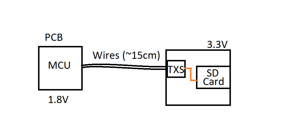
We have an application in which we need to interface an MCU running at 1.8V to an external board that has an SD Card at 3.3V. We are using SPI to communicate to the SD Card at very low frequencies (100kHz initialization, 6 MHz running). We were reviewing the TXS0206A and the TXS0108E for this application, as described in the diagram below:

We were using their respective dev boards to test this idea. Both circuits are connected directly to the SD card with no pullups of any sort using these SD cards and jumper wire length of ~5cm.

However, we are running into issues when the SD Card is being initialized at 100 kHz. I can see with a logic analyzer on both sides that the MCU is sending the correct initialization routine. However for some reason the SD card is replying incorrectly when the TX0206A or TX0108e is in between the MCU and the SD Card (for example, to CMD0, it replies with a 0x07, 0x03, and rarely with a 0x01. I also tested that the system works when I connect the SD card directly to the MCU and power the MCU @ 3.3V. This way I can know the logic is ok).

In another test, I powered the MCU and the SD Card at 3.3V and put both devices in between, to make sure that it was not the 1.8V having issues. I had the same error result.

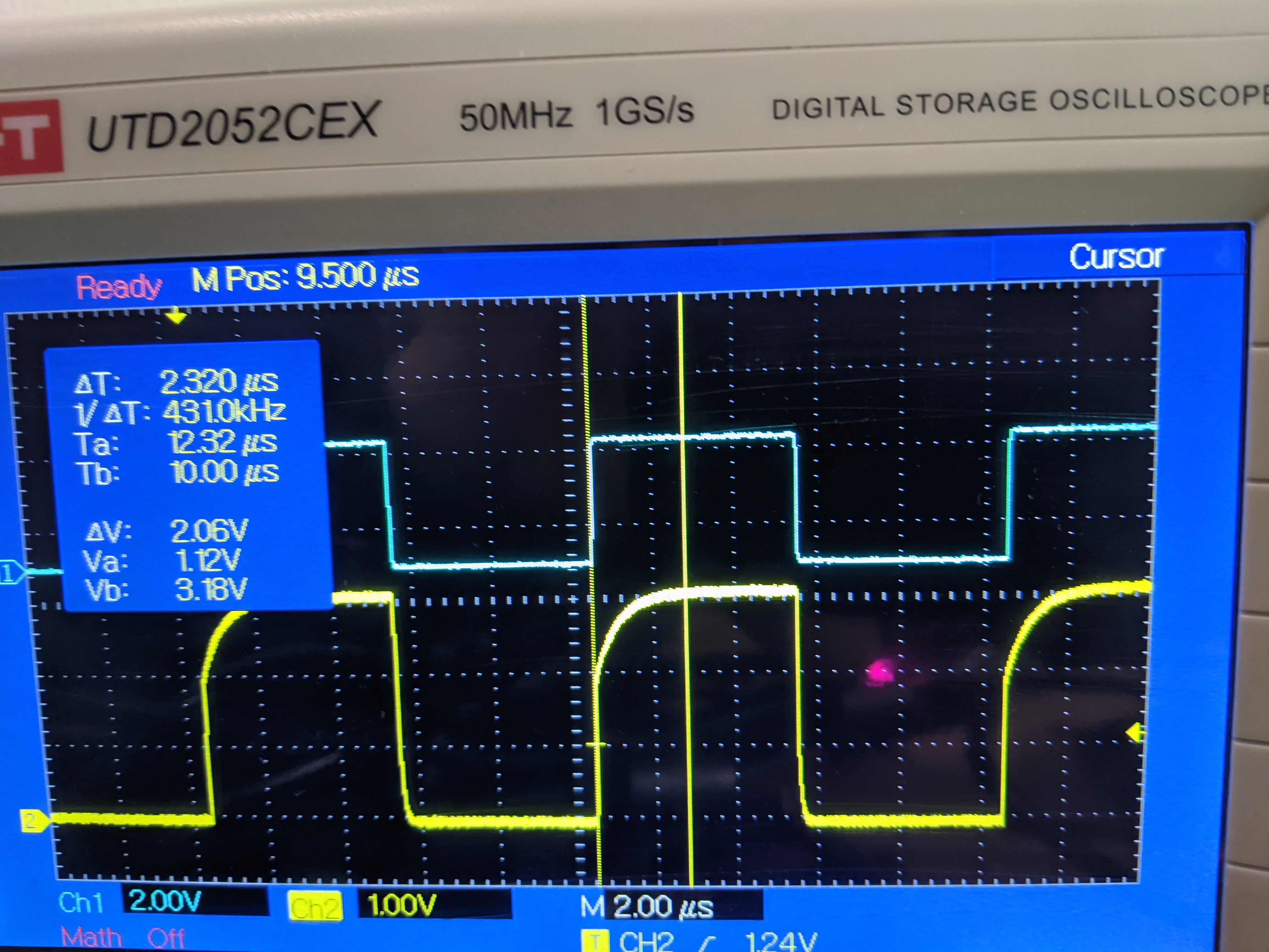
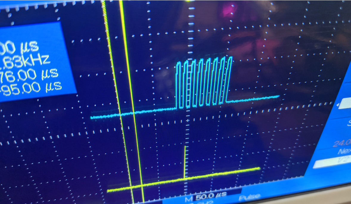
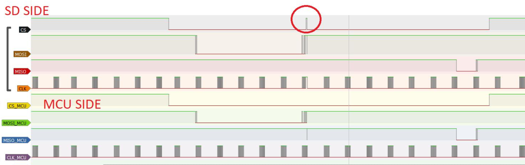
I have checked with the oscilloscope and cannot find any noise on both sides. However I do notice that sometimes there is a small glitch (<20ns) on the Chip Select line. As of now this is my only lead into what can cause the device to not function correctly.

Here is a capture from the logic analyzer on a failed initialization. The direct connection between an MCU@3.3V and the SD card does not present this glitch.

Searching the forum it seems this post was presenting something similar: e2e.ti.com/.../877297

I wanted to ask, what could I check to find the root cause? 

Also, would there be a better circuit for this application? Would it be better to use another IC, or another configuration?

Thank you!

  • I apologize, the pictures did not load correctly and in the middle of putting one the forum crashed and it seems it posted my message up to that point.

    Here is the diagram of what we want are testing. We basically want to be able to communicate to an SD card on another PCB from an MCU running at 1.8V

    Also, here is a scope taken of the chip select spike (yellow is CS, blue is CLK). Sorry for the weird angle, I can retake if more detail is needed.

    Here is a capture from the logic analyzer on a failed initialization. The direct connection between an MCU@3.3V and the SD card does not present this glitch.

    Searching the forum, it seems to me an issue similar to the following post:

    As a final note, I would like to ask what I can do to test the root cause, and more importantly, if TI could recommend me an IC to achieve the first diagram (SD communication from 1.8V to 3.3V at a distance of ~15cm-20cm, 6MHz max).

    Thank you!

  • Hello,

    I'll ask my translation expert to take a look at your question when we return to work on Monday. Please try to update the images that didn't load so he'll be able to see the whole issue.

    There's an FAQ on how to get images to properly post on the E2E forums: [FAQ] How to insert an image in your forum post.

  • Hey Eduardo,

    I can help find the root cause, but I will need more images (yours didnt come through). It's clear that that glitch is likely the cause of the communication error, but to understand it we will need to see a closer look around the spike with the input and output shown so we can hopefully find what is causing it.

    Saying that, this device isn't the best for your specific application. This translator is targeted for SD card applications but mainly around the SDIO interface. If you are using SPI then the SN74AXC4T774 device will be much better here as it actually increases drive strength and likely won't exhibit the same behavior.

  • Hi:

    Thank you very much for your help! I apologize, I went back to the initial post and posted the pictures there, but then I could not erase the second post - sorry for the confusion. The pictures on the first post has all the pictures I have.

    I will try to take scope captures when the spike happens. I will also look into using the chip you recommended and will post back here, thanks!

  • Hey Eduardo,

    I understand, thanks for the clarification. Looking forward to seeing how that new device works for you!

  • Hi Dylan:

    Thank you for your help. I am still awaiting the dev board of the IC you recommended.

    I did a quick test with the eval board of the TXS0108E. I had my dev board SD Lines hooked up to the dev board, and the dev board to the SD Card. The TXS is using the same level voltage on both sides. I know that if the connection Dev Board <=>SD Card is done directly, it works. If done thru the TCS device, it fails.

    What I proceeded to do was start connecting some wires directly to the MCU and leaving some on the TXS, to try to determine which line was the one that was making the communication fail. After this test, I found that the other lines work, but the CLK line does not (the CS, MISO and MOSI are connected thru the TXS device. If the CLK is connected directly the system works - if connected thru the TXS, it fails).

    I took two different captures of the CLK line explained below:

    1.)  (Blue Line: CLK on the MCU side, captured on the Dev Board pin. Yellow: SD CARD side, captured at the SD Card side. Wires to TXS EVM from Dev board and from SD Card are ~ 12cm total length).

    2.) Blue Line: CLK on the MCU side, captured on the Dev Board pin. Yellow: Right at the output of the TXS0108e dev board pin. Wires to the SD Card disconnected, so no capacitive load on this captures due to wires on the SD side).

    I see both captures very similar. I read the TXS device as internal pull-ups, but I wonder if the system would benefit from pull ups? I sadly don't have any at hand to do a quick test on the EVM.

    Once I have the IC you recommended I will post how it goes.

    Thanks!

  • Hey Eduardo,

    That signal doesn't look bad at all so I'm not sure why it would be causing an issue. The slow edge at towards the end of the rising edge is expected with the architecture of the TXS device. The new device will provide a nice clean edge since its better suited for push-pull signals.

    My only thought with the scope shots provided is that the BW is too low (I see 50 MHz). I would expect that wire to add inductance that could cause ringing when the one-shot is firing (they provide a low impedance path to GND increasing di/dt). So its possible you aren't seeing the ringing due to the low bandwidth. I recommend zooming in on one of those rising edges to see if there are any anomalies.

  • Hi Dylan:

    Thank you for all your help. I have tested the device and it works great, with wires up to 40cm (did not test longer). Thank you for your help. For anybody in the future that needs a similar application, this is a good solution. You can tie the CS line to the DIR of the MOSI line to allow the MOSI to be driven by other devices in the SPI line when the device is not selected - if not, then this driver will overpower the MOSI line and other components will not be able to drive it (which makes sense).

    As an almost unrelated sidenote, I found that most SD cards expect the dummy byte from the master to be 0xFF - if using another dummy byte, the response from the SD card might be incorrect (replying 0x03 or 0x07 when 0x01 was expected for a CMD0, for example). Some did not care on this dummy Byte value. Just putting it out there in case it helps somebody in the future.