Other Parts Discussed in Thread: HALCOGEN, , ARM-CGT, LAUNCHXL2-570LC43
I am receiving run-time ESM Group2-3 faults, which has the datasheet description of "All fatal bus error events. [Commonly caused by improper or incomplete ECC values in Flash.]"
I believe these are in fact Flash ECC faults as the EPC CAM registers are showing added addresses. My original application had multiple memory partitions, and when I reverted back to a single Flash0 partition, the number of CAM addresses went to 1, which suggests partitioning is making this worse.
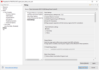
I have the CCS project setup to Auto ECC generation -- is there more I should do in CCS to properly load Flash with valid ECC bits?
My CoreEnableFlashEcc assembly code is the same as the code shown in the datasheet, and my setupFlash is the same as the C:\ti\Hercules\Hercules Safety MCU Demos\4.0.0\TMS570LC43x_target_sources\HALCoGen. There is a lot of code in C:\ti\Hercules\SafeTI Diagnostic Library\2.4.0, but there are also many conditional compilations, so it is unclear if different Flash-init functions should be called than the 2 above. Are these the only init-functions required?
Note I am running on the TMS570LC43x development board, and I had to add 3 waits states to FRDCNTL to get anything to execute, if that is relevant.
Thanks,
Jim