Other Parts Discussed in Thread: TIDEP-01014, TCAN4550, TMS570LS1224, HALCOGEN
Hi Team,
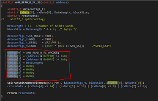
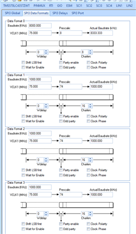
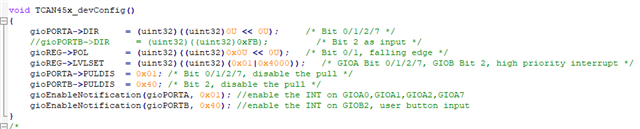
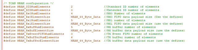
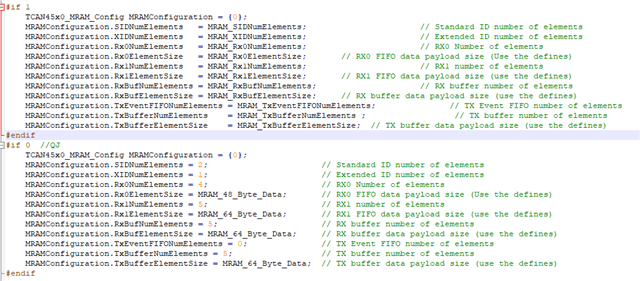
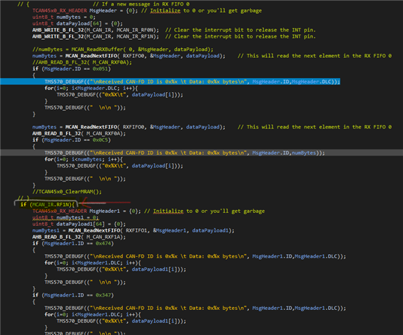
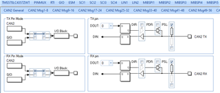
How to configure CANFD in TMS570LC4357

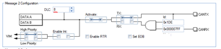
Couldn't increase a DLC more than 8. For CANFD I need 64 byte.
Please share me if you have any CANFD example code for TMS570 MCU.
Thanks in advance.