This thread has been locked.

If you have a related question, please click the "Ask a related question" button in the top right corner. The newly created question will be automatically linked to this question.

TMS570LC4357: TMS570LC4357: UART bootloader in TMS570LC4357 custom board.

Part Number: TMS570LC4357
Other Parts Discussed in Thread: HALCOGEN

Hi QJ Wang,

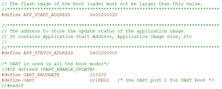
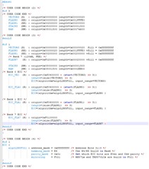
Please guide me on Hardware circuit for UART Bootloader other then SCI RX and SCI TX pin, 

Did we need to connect any other pin as per the JTAG. 

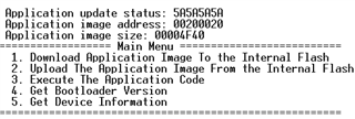
The UART bootloader works only in UART1 of HDK . 

It is not working in SCI 2 or SCI3 or SCI4 

  • Hi Santhosh,

    To use SCI2/3/4, you need a UART transceiver to attached to SCI TX/RX pins.

  • Yes, I have connected the UART SCI 2 TX/RX pins , Is it FORCED_UPDATE_PIN (GIOA7) in  bl_config.h need to be used for Downloading the Application code through UART bootloader ?

    SCI 2 is configured and it is working fine. without debugger it is not working fine. 

    What is the purpose of FORCED_UPDATE_PIN?

    How to configure the APP_START_ADDRESS and APP_STATUS_ADDRESS  

    HL_sys_link.cmd file of UART bootloader 

    /* Memory Map */

    MEMORY
    {
    /* USER CODE BEGIN (2) */
    #if 0
    /* USER CODE END */
    /* USER CODE BEGIN (3) */
    #endif

    #if 1
    VECTORS (X) : origin=0x00000000 length=0x00000020 fill = 0xffffffff
    FLASH0 (RX) : origin=0x00000020 length=0x001FFFE0 vfill = 0xffffffff
    FLASH1 (RX) : origin=0x00200000 length=0x00200000 vfill = 0xffffffff
    /* Bank 7 (128kB, FEE) */
    FLASH7 (R) : origin=0xF0200000 length=0x00020000 vfill = 0xffffffff

    STACKS (RW) : origin=0x08000000 length=0x00001500
    RAM (RW) : origin=0x08001500 length=0x0002EB00
    /* Bank 0 ECC */
    ECC_VEC (R) : origin=(0xf0400000 + (start(VECTORS) >> 3))
    length=(size(VECTORS) >> 3)
    ECC={algorithm=algoL2R5F021, input_range=VECTORS}

    ECC_FLA0 (R) : origin=(0xf0400000 + (start(FLASH0) >> 3))
    length=(size(FLASH0) >> 3)
    ECC={algorithm=algoL2R5F021, input_range=FLASH0 }

    /* Bank 1 ECC */
    ECC_FLA1 (R) : origin=(0xf0400000 + (start(FLASH1) >> 3))
    length=(size(FLASH1) >> 3)
    ECC={algorithm=algoL2R5F021, input_range=FLASH1 }

    /* Bank 7 ECC */
    ECC_FLA7 (R) : origin=0xF0100000
    length=(size(FLASH7) >> 3)
    ECC={algorithm=algoL2R5F021, input_range=FLASH7 }
    #endif
    /* USER CODE END */
    }

    /* USER CODE BEGIN (4) */
    #if 1
    ECC {
    algoL2R5F021 : address_mask = 0xfffffff8 /* Address Bits 31:3 */
    hamming_mask = R4 /* Use R4/R5 build in Mask */
    parity_mask = 0x0c /* Set which ECC bits are Even and Odd parity */
    mirroring = F021 /* RM57Lx and TMS570LCx are build in F021 */
    }
    #endif
    /* USER CODE END */


    /*----------------------------------------------------------------------------*/
    /* Section Configuration */

    SECTIONS
    {
    /* USER CODE BEGIN (5) */
    #if 0

    /* USER CODE BEGIN (6) */
    #endif

    #if 1
    .intvecs : {} palign=8 > VECTORS
    flashAPI:
    {
    .\Boot\Fapi_UserDefinedFunctions.obj (.text)
    .\Boot\bl_flash.obj (.text)
    --library = F021_API_CortexR4_BE_L2FMC.lib (.text)
    } palign=8 load = FLASH0 |FLASH1, run = RAM, LOAD_START(apiLoadStart), RUN_START(apiRunStart), SIZE(apiLoadSize)

    .text : {} palign=8 > FLASH0 |FLASH1 /*Initialized executable code and constants*/
    .const : {} palign=8 load=FLASH0 |FLASH1, run = RAM, LOAD_START(constLoadStart), RUN_START(constRunStart), SIZE(constLoadSize) /*Initialized constant data (e.g. const flash_sectors[..] = )*/
    .cinit : {} palign=8 > FLASH0 | FLASH1 /* Tables for explicitly initialized global and static variables */
    .pinit : {} palign=8 > FLASH0 | FLASH1 /* C++ global constructor addresses */
    .bss : {} > RAM /* Uninitialized global and static variables */
    .data : {} > RAM /* Global and static non-const variables that are explicitly initialized. */
    .sysmem : {} > RAM /* Memory pool (heap) for dynamic memory allocation */
    #endif

    /* USER CODE END */
    }

    /* USER CODE BEGIN (7) */
    /* USER CODE END */


    /*----------------------------------------------------------------------------*/
    /* Misc */

    /* USER CODE BEGIN (8) */
    /* USER CODE END */
    /*----------------------------------------------------------------------------*/

    Application link file is 

    MEMORY
    {
    /* USER CODE BEGIN (2) */
    /* USER CODE END */
    VECTORS (X) : origin=0x00200000 length=0x00000020
    FLASH0 (RX) : origin=0x00000000 length=0x00200000
    FLASH1 (RX) : origin=0x00200020 length=0x001FFFE0
    STACKS (RW) : origin=0x08080000 length=0x00001500
    RAM (RW) : origin=0x08081500 length=0x0007EB00

    /* USER CODE BEGIN (3) */
    /* USER CODE END */
    }

    /* USER CODE BEGIN (4) */
    /* USER CODE END */


    /*----------------------------------------------------------------------------*/
    /* Section Configuration */

    SECTIONS
    {
    /* USER CODE BEGIN (5) */
    /* USER CODE END */
    .intvecs : {} > VECTORS
    .text align(32) : {} > FLASH1
    .const align(32) : {} > FLASH1
    .cinit align(32) : {} > FLASH1
    .pinit align(32) : {} > FLASH1
    .bss : {} > RAM
    .data : {} > RAM
    .sysmem : {} > RAM

    /* USER CODE BEGIN (6) */
    /* USER CODE END */
    }

    Can you confirm me the Memory Map for both Application and bootloader is correct ?

  • Is it FORCED_UPDATE_PIN (GIOA7) in  bl_config.h need to be used for Downloading the Application code through UART bootloader ?

    SCI 2 is configured and it is working fine. without debugger it is not working fine. 

    What is the purpose of FORCED_UPDATE_PIN?

    After a reset, the bootloader checks to see if an application update should be performed by calling CheckForceUpdate(). If am update is not required, the application at the APP_START_ADDRESS is called. 

    The check for an application update (in CheckForceUpdate()) consists of checking the Update STATUS at APP_STATUS_ADDRESS and optionally checking the state of a GPIO pin. 

    The GPIO pin check can be enabled with ENABLE_UPDATE_CHECK in the bl_config.h header file, in which case an update can be forced by changing the state of a GPIO pin (for example, with a push button on HDK).

    If the application is valid (the STATUS = 0x5A5A5A5A) and the GPIO pin is not requesting an update, the application is called. Otherwise, an update is started by entering the main loop of the boot loader.

    Can you confirm me the Memory Map for both Application and bootloader is correct ?

    Please check the allocate the output sections in bootloader to FLASH0 rather than FLASH0 | FLASH1

    flashAPI:
    {
    .\Boot\Fapi_UserDefinedFunctions.obj (.text)
    .\Boot\bl_flash.obj (.text)
    --library = F021_API_CortexR4_BE_L2FMC.lib (.text)
    } palign=8 load = FLASH0, run = RAM, LOAD_START(apiLoadStart), RUN_START(apiRunStart), SIZE(apiLoadSize)

    .text : {} palign=8 > FLASH0 /*Initialized executable code and constants*/
    .const : {} palign=8 load=FLASH0, run = RAM, LOAD_START(constLoadStart), RUN_START(constRunStart), SIZE(constLoadSize) /*Initialized constant data (e.g. const flash_sectors[..] = )*/
    .cinit : {} palign=8 > FLASH0 /* Tables for explicitly initialized global and static variables */
    .pinit : {} palign=8 > FLASH0 /* C++ global constructor addresses */
    .bss : {} > RAM /* Uninitialized global and static variables */
    .data : {} > RAM /* Global and static non-const variables that are explicitly initialized. */
    .sysmem : {} > RAM /* Memory pool (heap) for dynamic memory allocation */
    #endif

    /* USER CODE END */

  • Hi QJ Wang,

    After a reset, the bootloader checks to see if an application update should be performed by calling CheckForceUpdate(). If am update is not required, the application at the APP_START_ADDRESS is called. 

    -- After a software reset from IDE, the bootloader checks CheckForceUpdate() and I enabled DEBUG_MSG == 1 but it goes to the UART function but it doesn't displayed in UART which is connected to HyperTerminal.

    and it is entering to CheckGPIOForceUpdate() function FORCED_UPDATE_PIN is not set  from myside. So it Jumps to application when I am doing set by set using debug and  the application LED blink is working fine.

    But if I runs it without debug then it is entering to UART-getKey which is excepting my input from UART but I couldn't see anything in UART HyperTerminal.

    Please check this Memory Mapping from Bootloader 

    #if 1
    VECTORS (X) : origin=0x00000000 length=0x00000020 fill = 0xffffffff
    FLASH0 (RX) : origin=0x00000020 length=0x001FFFE0 vfill = 0xffffffff
    FLASH1 (RX) : origin=0x00200000 length=0x00200000 vfill = 0xffffffff
    /* Bank 7 (128kB, FEE) */
    FLASH7 (R) : origin=0xF0200000 length=0x00020000 vfill = 0xffffffff

    STACKS (RW) : origin=0x08000000 length=0x00001500
    RAM (RW) : origin=0x08001500 length=0x0002EB00

    and from LED blinking application code.

    MEMORY
    {
    /* USER CODE BEGIN (2) */
    /* USER CODE END */
    VECTORS (X) : origin=0x00200000 length=0x00000020
    FLASH0 (RX) : origin=0x00000000 length=0x00200000
    FLASH1 (RX) : origin=0x00200020 length=0x001FFFE0
    STACKS (RW) : origin=0x08080000 length=0x00001500
    RAM (RW) : origin=0x08081500 length=0x0007EB00

    /* USER CODE BEGIN (3) */
    /* USER CODE END */
    }

    In this my doubt is FLASH0 is starts from 0x00000020  in bootloader length is 0x001FFFE0

    adding both FLASH0 and length it should be FLASH1 is 0x00200000 is Application code

    #define APP_START_ADDRESS 0x00200020

    #define APP_STATUS_ADDRESS 0x00200000 

    Is this correct 

    Please confirm the memory map. 

    Thanks in advance.

  • and it is entering to CheckGPIOForceUpdate() function FORCED_UPDATE_PIN is not set  from myside. So it Jumps to application when I am doing set by set using debug and  the application LED blink is working fine.

    Does this mean that it jumps the application correctly? Did you program the application image using bootloader?

    I couldn't see anything in UART HyperTerminal.

    Does the terminal have the same baudrate and stop bit as used in your code? Can you display any message on the Terminal?

    In this my doubt is FLASH0 is starts from 0x00000020  in bootloader length is 0x001FFFE0

    The bootloader should not be that big (0x1FFE0). It normally fit in the first , and should fit into the first 4 flash sectors (64KB). 

  • :Does this mean that it jumps the application correctly? Did you program the application image using bootloader?

    Yes, Sometimes if I debug it properly goes to Application code and working fine.

    Yes, I have program the application image using bootloader.

    :Does the terminal have the same baudrate and stop bit as used in your code? Can you display any message on the Terminal?

    Yes, I can seen the message which displays the option of the UART bootloader and gets the input from UART and it works fine, But after it goes to application code through 3rd option. 

    Next cycle it doesn't display in HyperTerminal properly.

    Now, the Application code LED is blinking fine.

    Then, I have given software reset.

    It goes through CheckGPIOForceUpdate function

    without FORCED INPUT 

    UpdaterUART();

    Now, it is stuck in below UART_getKey() function waiting for input from UART but HyperTerminal 

    After hardware reset, It jumps to application 

    but application code it doesn't work properly. Not LED blinking. 

    UART Bootloader Memory:

    Application memory:

    Please help me to fix this issue 

    Thanks in advance

    Santhosh

  • Hi Santhosh,

    Please change:

        VECTORS (X)    : origin=0x0020000 length=0x00000020

    to:

        VECTORS (X)    : origin=0x0020020 length=0x00000020

    Since the application image in programmed to the flash section starting at 0x20020 rather than 0x20000.

  • Hi QJ Wang,

    Did I need to change only in application memory HL_sys_link.cmd file 

    Application memory:

    Both VECTORS origin and FLASH1 origin should be same?

    UART Bootloader Memory:

    In UART Bootloader Memory, FLASH1 (RX) origin is same as application memory origin ?

    Please confirm

    Thanks in Advance.

    Santhosh

  • Hi QJ Wang, 

    Please share me the memory mapping for both Application memory and bootloader memory with HL_sys_link.cmd file and the HL_sys_startup.c file which start  function  _c_int00 are same in both the application and bootloader code.

    How to allocate memory for VECTOR, STACK and RAM are needed for both application and bootloader code ?

    The Application code is executing if the XDS110 debug probe is connected and after system reset from IDE also works fine.

    SCI2 is UART for UART bootloader

    But I remove the XDS110 debug probe and just use the SCI2 UART for UART bootloader then it is not working fine.

    Application 

    Bootloader

    Memory

    Sections

    Please check and confirm me.

    I got stuck in UART bootloader 

    Thanks in advance

    Santhosh

  • Hi Santhosh,

    The FLASH1 memory allocation in your bootloader linker cmd file should be:

    FLASH1  (RX) : origin=0x00200000  length=0x200000

    Everything else looks fine.

  • Hi QJ Wang,

    My issue is resolved for UART bootloader. the application code is executing through UART Bootloader now. 

    I have query on Application side code to switch back to Bootloader section to reprogrammable option for different application code to burn through UART bootloader.

    Please suggest any idea. 

    Thanks in advance.

  • Hi QJ Wang,

    If I need to reprogramming the Application code, How to move UART bootloader from Application , then In the bootloader code how to judge it as Normal reset or reprogramming reset?

    How to access the Flash Bank 1 from application code using F021_API "F021_API_CortexR4_BE_L2FMC_V3D16.lib"

    In my application main code, I have called Fapi_BlockRead function after entering to Fapi_doMarginReadByByte then randomly gone out of the code. 

    FapiReturn = Fapi_BlockRead(g_ulUpdateStatusAddr,(unsigned long)&g_pulUpdateSuccess,g_ulUpdateBufferSize);

    but this function is in the lib file.

    Fapi_doMarginReadByByte((uint8_t *)src,
    (uint8_t *)dst,
    (uint32_t) bytes, //16
    Fapi_NormalRead);

    Please support to find the issue in this function or linking 

  • Normal reset or reprogramming reset?

    Reprogramming reset might be a SW reset.

    after entering to Fapi_doMarginReadByByte then randomly gone out of the code. 

    Why do you call MarginRead API in your application? You need to copy the Flash API to RAM and run from RAM.

  • Hi QJ Wang,
    Reprogramming reset might be a SW reset.
    g_ulbootTransferAddress = (uint32_t)BOOT_START_ADDRESS;
    ((void (*)(void))g_ulbootTransferAddress)();
    I have used the function pointer for jumping to a Bootloader from Application
    How to found reprogramming  as SW reset using a Register ?
    Why do you call MarginRead API in your application? You need to copy the Flash API to RAM and run from RAM.
    It is called to write and read a Flash memory to send a information that the application is intended to request for reprogramming. 
    If normal reset happen the bootloader should allow to enter application directly by checking the Flash memory of
    #define APP_STATUS_ADDRESS 0x00200000.
    In case of application request to reprogram then it should enter to UART options of programming. 
    How to send a information to bootloader from application for request for reprogramming?
    Thanks in Advance
    Santhosh
  • How to send a information to bootloader from application for request for reprogramming?

    You can share teh information between application and bootloader using EERPOM. The HALCoGen can generate FEE driver for EEPROM read and write.