This thread has been locked.

If you have a related question, please click the "Ask a related question" button in the top right corner. The newly created question will be automatically linked to this question.

AM2432: SYSCONFIG Tool Clarifying Questions

Part Number: AM2432
Other Parts Discussed in Thread: SYSCONFIG

Hi Team,

My customer is confused about the SYSCONFIG tool regarding the notation and its differences.

1.

It seems that there are a variety of different pages to set the pins depending on the initial settings in the 'Welcome to SysConfig' page.

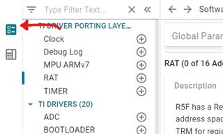
For example, If they select something for the 'Software Product' as below,

then they will get the two tabs (Software, Reserved Peripherals) as below,

However if they don't select a 'Software Product' in the 'Welcome to SysConfig' page, they get different tabs, 'Peripherals' and 'Device Settings', as below.

They cannot simultaneously have both set at the same time in the configuration script, so they want to confirm that 1. they are using the tool correctly? (ie. should they select or not select the software product first) 2. is there a difference in the code generated from these two different pages when they do or do not select the software product.

2. As a continuation of the question above, in the scenario that they select a 'Software Product' and they have the two tabs (Software, Reserved Peripherals), if they ADD SPI3 in the 'Software' tab, and they also try to ADD SPI3 in the 'Reserved Peripherals', they get a conflict error. How do they differentiate which tab to ADD the SPI? Can they add it in both or are they limited to one of the tabs?

Best regards,

Mari Tsunoda

  • Hey Mari,

    1.a) Yes, the customer is using the tool correctly. The two options/views they see are the MCU+SDK Software Product (top option) or the raw device pinmux view (bottom option).
    1.b) MCU+SDK Software Product provides all functional configuration code for an IP, whereas the raw pinmux only enables auto-generation of the pinmux configuration code. The MCU+ SDK Software Product for a given device will generate the pinmux configuration code by default for the associated peripheral pins.

     2) If a peripheral is going to use example SDK code, it should be configured in the Software tab when available. The Reserved Peripherals tab was added to allow users to lock-down specific pins for peripherals that aren't currently supported in the Software tab, without needed to worry about the auto-muxing re-assigning the pin when solving for pinmux options. The conflict error occurs because you are "Reserving" the SPI3 signals in one tab, and then also trying to re-assign them to function in the Software tab. Customer should always add a peripheral in the Software Tab if available.

    Best Regards,

    Zackary Fleenor

  • Hi Zackary,

    Thank you again for the quick responses.

    A few follow-up questions:

    1) 

    the raw pinmux only enables auto-generation of the pinmux configuration code

    I'm still a little confused about the differences between the auto-generated pinmux configuration code vs. the full functional configuration code. Could you elaborate more on this?

    2)

    Customer should always add a peripheral in the Software Tab if available.

    Just a hypothetical, but would they be able to assign all pins in the 'Reserved Peripherals' tab if they wanted to instead of the 'Software' tab? Is there difference in setting everything in the 'Software' tab vs the 'Reserved Peripherals' tab? 

    3)

    They had a question about the clocks in SysConfig. 

    As an example, they showed us this page with the OSPI and it says the clock frequency and the clock divider, but what is the input source of this clock?

    Best regards,

    Mari

  • Hey Mari,

    1) The full functional configuration code is still also an auto-generated file (via Software view) and includes the subset files required for pinmux configuration by default.

    2) If customer assigned all modules in Reserved Peripherals tab, then they would be missing all the additional auto-generated configuration files that are output from assigning in the Software tab.

    3) Please refer to the AM263x TRM (https://www.ti.com/lit/pdf/spruj17) Device Configuration - Clocking chapter for comprehensive details on the device clock tree structure and related configuration parameters. Please feel free to create a new thread if further questions arise regarding these clocking details after reviewing the chapter content.

    Best Regards,

    Zackary Fleenor