This thread has been locked.

If you have a related question, please click the "Ask a related question" button in the top right corner. The newly created question will be automatically linked to this question.

TM4C129ENCPDT: Programming the device using Ethernet via LM Flash Programmer

Part Number: TM4C129ENCPDT
Other Parts Discussed in Thread: EK-TM4C1294XL

Hi,

We are trying to program the device via Ethernet.

We are able to talk to the device via Ethernet port without any problem. We have programmed the device using ethernet port when the device is connected directly to the computer using Ethrenet port. We installed the device in a crowdy network that has thousands of devices and able to communicate without any problem.

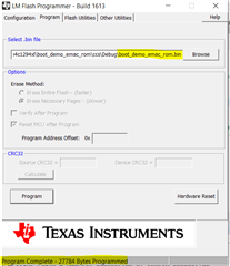
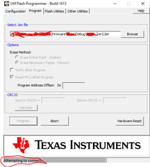
However when we attempt to program it using the LM Flash Programmer- Build 1613. By pressing the Program button, it will go into "Attempting to connect" and will stay there forever.

I just want to repeat, we were able to program the device when directly connected to the computer via local Ethernet port. However we had seen it would still take few minutes to discover the device when connected to the computer directly.

Following is the snapshot of the LM Flash Programmer;

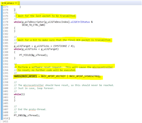
I dont think it is code related problem for that fact that we are able to program when connected directly to computer via Ethernet port. However, I share the sequence the processor goes through when invoked for remote programming mode;

//IntMasterDisable();
HWREG(NVIC_DIS0) = 0xFFFFFFFF;
HWREG(NVIC_DIS1) = 0xFFFFFFFF;
HWREG(NVIC_DIS2) = 0xFFFFFFFF;
HWREG(NVIC_DIS3) = 0xFFFFFFFF;
HWREG(NVIC_DIS4) = 0xFFFFFFFF;
ROM_SysTickIntDisable();
ROM_SysTickDisable();

ROM_UpdateEMAC(sys_clock);

I thank you all for your time and help.

Regars,

Sahil

  • I just noticed my PC is on different subnet and the device is on different subnet. Could that be a problem ? Are they both required to be on same subnet ?

  • Hi Sahil,

    FYI: Cisco switches will not typically send broadcasts packets across other VLANS without IP helper being set enabled. That is a protective measure to stop broadcast storms from one subnet bring the entire network down from a rogue ethernet card in full continuous broadcast mode. That is likely why LM Flash does not get the BootP magic packet request to FTP data Get request.

    Regards,

  • Hi,

      That is very likely the reason for the problem. Please keep your device and PC on the subnet and see if that resolves the issue. Please also show your wireshark capture. 

  • Okay thank you. I noticed the processor will program in remote mode over ethernet but it will not reset. I have to manually power cycle the device. Is there any line of code missing in my code (See the code in the main thread) I have checked mark to reset the processor after programming in the LM Flash Programmer as well.

  • Hi,

      Reading the bl_emac.c bootloader code, it will reset the MCU after the TFTP transfer is complete. Are you using the ROM-based bootloader or the flash-based bootloader. 

      Also to give you a heads-up, I will be out of office until next Tuesday starting tomorrow. 

  • I am not sure but looking at ROM_UpdateEMAC(sys_clock); in the main post, it seems it is Rom based bootloader ?

    or

    please guide how to identify otherwise ?

    Thanks

  • Hi Sahil,

      The bl_emac.c that I was referring to is the flash-based bootloader. When you call ROM_UpdateEMAC(), it is executing the bootloader stored in the ROM. I suppose your application starts at address 0x0, correct? I believe regardless of flash or ROM-based bootloader, it will initiate a software reset at the end. I just tried the example at C:\ti\TivaWare_C_Series-2.2.0.295\examples\boards\ek-tm4c1294xl\boot_demo_emac_rom and I could repeatedly hit "Program" button in LM flash programmer and it will update the firmware again and again. This means after the update, the processor is reset and start executing  application code to wait for the next update by listening for the magic to arrive from the host computer. Please try the boot_demo_emac_rom example and compare with your own code. 

  • Here is my .cmd file.

    I think it is starting at 0x0 where the Flash (RX): Origin is mentioned

    --retain=g_pfnVectors
    
    MEMORY
    {
    FLASH (RX) : origin = 0x00000000, length = 0x00100000
    SRAM (RWX) : origin = 0x20000000, length = 0x00040000
    }
    
    /* The following command line options are set as part of the CCS project. */
    /* If you are building using the command line, or for some reason want to */
    /* define them here, you can uncomment and modify these lines as needed. */
    /* If you are using CCS for building, it is probably better to make any such */
    /* modifications in your CCS project and leave this file alone. */
    /* */
    /* --heap_size=0 */
    /* --stack_size=256 */
    /* --library=rtsv7M4_T_le_eabi.lib */
    
    /* Section allocation in memory */
    
    SECTIONS
    {
    .intvecs: > 0x00000000
    .text : > FLASH
    .const : > FLASH
    .cinit : > FLASH
    .pinit : > FLASH
    .init_array : > FLASH
    
    .vtable : > 0x20000000
    .data : > SRAM
    .bss : > SRAM
    .sysmem : > SRAM
    .stack : > SRAM
    }

    Please note my application is based on FreeRTOS. Not sure if it has a relation to it ?

  • Yes, your application starts from 0x0. Whether it is due to FreeRTOS, I don't know. Why don't you insert some code to toggle a pin right after reset? Does your code ever reach there?

  • Well I am using ROM based bootloader. So I dont know what do you mean by toggling a pin right after Reset. I have already an LED toggling when I power cycle the device.

  • If you don't power cycle the device then what happens? If your debugger connect to the target, where is the program counter? What is the processor doing at that time?

    i mean in your application firmware, insert some code to toggle a pin before you start your FreeRTOS scheduler. After the firmware update, if a reset happens, then the processor will jump to the reset vector and then start executing your code. If you see your pin toggled then it means it should have done the reset sequence. 

  • So when i download the firmware via Ethernet. The LM Flash programmer says "Complete" and the LED is off and not toggling until I power cycle. after that I read via Ethernet the firmware version and it does report the new version number of the firmware which means it successfully programmed the device however somewhere in the Reset sequence it hangs up.

    Let me blink an LED just before the FreeRTOS scheduler and report you back.

    I have not used JTAG to interrupt a processor once programmed via Ethernet.  Can you please guide how can I interrupt the processor when it is programmed via Ethernet and check the PC register ?

  • I was able to capture the event using JTAG.

    It goes into FaultISR()

    static void
    FaultISR(void)
    {
        //
        // Enter an infinite loop.
        //
        while(1)
        {
        }
    }

    It doesnt reach to the point to Turn On the LED just before the scheduler. 

  • You will need to debug what caused the fault to happen. Here is an app note that shows the technique. https://www.ti.com/lit/pdf/spma043

  • I dont understand power cycling and sending a Reset via Ethernet basically the same thing. Why would the processor not going into FaultISR() when Power cycled vs Sending a Reset.

  • I'm not really sure either. A lot of times, the fault is because of either lack of sufficient stack size or the peripheral you are accessing is not yet enabled.  Some suggestions:

      1. Use the app note techniques to debug what caused your faults. Is it because of the stack overflow or you are accessing a peripheral that is not enabled. 

      2. Try the example I mentioned earlier and make sure it works and then integrate into your FreeRTOS environment and try again. Can you repeat the same faults. If it works, then compare with your own code. 

      Again, I'm about to leave for the day and will not be able to reply until next Tuesday. 


  • Thank you Charles.

    I was able to capture the NVIC FAULT STAT. It raises Instruction Access Violation. Which I dont understand why it would do when we program remotely using ROM based boot loader. 

    Please see picture bellow;

  • See below. 

    I think the potential reason could be:

    - Branch to regions that are not defined in the MPU or defined as non-executable.

    - Invalid return due to corrupted stack content.

    - Incorrect entry in the exception vector table.

  • Which I dont understand why it would do when we program remotely using ROM based boot loader. 

    Perhaps try Wire Shark to be sure TFTP server receives file transfer complete from the client. BTW all network broadcasts stop at the router, for that reason bootloader TFTP client/server will not work via the internet.

    There are versions of TFTP servers that seemingly do not broadcast and download files across the internet onto a Windows TFTP client.  Seemingly it works across the internet since the source and destination IP address is included. https://www.tftp-server.com/tftp-client.html