This thread has been locked.

If you have a related question, please click the "Ask a related question" button in the top right corner. The newly created question will be automatically linked to this question.

TM4C129ENCZAD: What to do when the device is not found

Part Number: TM4C129ENCZAD
Other Parts Discussed in Thread: UNIFLASH, TMDSEMU110-U, , TM4C1294NCPDT, AWR1843, AWR1843BOOST, MSP432E401Y

The device is not found by typing the command below.
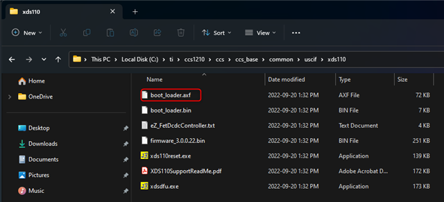
If you connect TM4C129x directly with USB after bootloader.bin with UniFlash, it will be in the form of .


What should I do?

command
xdsdfu.exe -e

article that was written
Scanning USB buses for supported XDS110 devices...


Found 0 devices.

  • Hello,

    Please see the Troubleshooting section of:

    https://dev.ti.com/tirex/explore/node?node=A__ALFqIj4dX6S.TZRERoSphA__xdsdebugprobes__FUz-xrs__LATEST

    If you connect TM4C129x directly with USB after bootloader.bin with UniFlash,

    Was the XDS110 probe working fine prior to flash the bootloader?

    Thanks

    ki

  • Yes, it is.

    The device was detected when the TM4C129x itself was plugged into USB.

    However, it was described as Sterallis ........Firmware Upgrade.

  • Are you using a standalone XDS110 probe or an onboard one that is integrated on to a board? If is an onboard one, which exact board? Is it a custom board or an standard EVM or LanchPad?

  • Yes, I have the XDS110 in standalone form.

    It is TMDSEMU110-U.

    Ultimately, I want to connect the TM4C129x to my PC via USB and the other ICs via UART.
    Therefore, I would like to complete the port opening.

  • Yes, I have the XDS110 in standalone form.

    It is TMDSEMU110-U.

    Thank you for clarifying.

    What is your exact target board that you are trying to use TMDSEMU110-U with to debug?

  • I see that you have a related thread:

    https://e2e.ti.com/support/microcontrollers/arm-based-microcontrollers-group/arm-based-microcontrollers/f/arm-based-microcontrollers-forum/1185739/tm4c129enczad-why-strallis-device-firmware-upgrade-is-missing

    Let us continue discussion here.

    I am a bit confused. Can you provide in exact detail your environment and what you are trying to do? Based on the information I have, I suspect:

    You are using a standalone TMDSEMU110-U to attempt to flash a new TM4C129ENCZAD chip. Is this correct? If so, are you trying to create your own custom XDS110 probe? If so, is this custom XDS110 integrated on to a target board? Note that the XDS110 has typically used a TM4C1294NCPDT are you trying to substitute it with a TM4C129ENCZAD?

  • Note that TM4C1294NCPDT and TM4C129ENCZAD is not pin compatible. For example, step 2 of the "Flashing the bootloader" section of the XDS110 page mentiones:

    2. Connect the JTAG TDO pin of the XDS110 TM4C1294NCPDT device (pin 97 of the 128-pin package device) to ground.

    Pin 97 of the 128-pin package of the TM4C1294NCPDT corresponds to PC3. That would be Ball C14 of the TM4C129ENCZAD package.

    Assuming you are creatong your own custom XDS110 probe, can you provide the schematics for it so engineering can take a look?

  • Hello, I would like to ask you a question here.

    First, I want TM4C129ENCZAD to have the function of XDS110 Emulator.

    The reason I want to have it is because I want to write programs to the AWR1843, transfer data, and use it as a debugger.
    (I want to have the same function as AWR1843Boost.)

    I thought I needed the TMDSEMU110-U to implement that emulator.
    I have done the wiring in the schematic below.

    I would like to know what is required to actually incorporate the XDS110Emulator into the TM4C129ENCZAD.

  • Sorry, I was worried again, so I checked the implementation of xds110 Emulator.

    I tried the following steps.

    1. I connected TM4C129ENCZAD and USB.

    2. I opened the command prompt and moved to the following hierarchy.

    cd C:\ti\ccs1120\ccs\ccs_base\common\uscif\xds110

    3. Next, I browsed for connected devices.
    C:\ti\ccs1120\ccs\ccs_base\common\uscif\xds110>xdsdfu.exe -e

    USB Device Firmware Upgrade Utility
    Copyright (c) 2008-2019 Texas Instruments Incorporated.

    Scanning USB buses for supported XDS110 devices...


    <<<< Device 0 >>>>

    VID: 0x1cbe PID: 0x00ff
    Device Name: Tiva Device Firmware Update
    Manufacturer: Texas Instruments Incorporated
    Serial Number: 00000000
    Mode: DFU

    Found 1 device.

    4. Next, I loaded firmware.bin.

    C:\ti\ccs1120\ccs\ccs_base\common\uscif\xds110>xdsdfu.exe -f firmware_3.0.0.20.bin -r

    USB Device Firmware Upgrade Utility
    Copyright (c) 2008-2019 Texas Instruments Incorporated.

    Scanning USB buses for supported XDS110 devices...

    Downloading firmware_3.0.0.20.bin to device...

    5. Did device detection again.

    C:\ti\ccs1120\ccs\ccs_base\common\uscif\xds110>xdsdfu.exe -e

    USB Device Firmware Upgrade Utility
    Copyright (c) 2008-2019 Texas Instruments Incorporated.

    Scanning USB buses for supported XDS110 devices...


    <<<< Device 0 >>>>

    VID: 0x1cbe PID: 0x00ff
    Device Name: Tiva Device Firmware Update
    Manufacturer: Texas Instruments Incorporated
    Serial Number: 00000000
    Mode: DFU

    Found 1 device.

    The above procedure did not switch to xds110 mode.

  • Can you attach a JTAG probe to the TM4C129ENCZAD? If so, can you try using your TMDSEMU110-U to connect CCS to the TM4C129ENCZAD and then load the boot_loader.axf file via CCS?  

  • I don't think it's a difficult thing to think about just in terms of design.

    However, DEBUGProbe (TMDSEMU110-U) has stopped turning on, so I can't try it right away.
    (Debug probes are currently out of stock.)

    By the way, I would also like to know where the file you posted is located.

  • By the way, I would also like to know where the file you posted is located.

    If you are referring to boot_loader.axf, it is in the same directory as the xdsdfu utility:

  • Mr. Ki

    Thank you for teaching me.

    Found it after checking.
    By the way, do I need a Probe with XDS110 Emulator to write files posted to TM4C129ENCZAD from CCS?
    (TMDSEMU110-U as an example)

    If possible, I would like to connect the TM4C129ENCZAD and USB directly and write the .axf file.

  • The *.axf file is basically the *.bin file with the debug information. Hence it is only to be used when loading it using the "Program load" option with CCS via JTAG.

    For USB only interface, you would need to use "xdsdfu -b boot_loader.bin -r" from the command line. But I believe that did not work for you in the past. Can you try again?

  • Hi, thanks for your reply.

    You said:
    For USB only interface, you would need to use "xdsdfu -b boot_loader.bin -r" from the command line. But I believe that did not work for you in the past. Can you try again?

    I checked again.

    Below is the command procedure. (Firmware has been upgraded for the convenience of CCS.)

    -------------------------------------------------- ---------------------------------------
    C:\ti\ccs1210\ccs\ccs_base\common\uscif\xds110>xdsdfu.exe -e

    USB Device Firmware Upgrade Utility
    Copyright (c) 2008-2019 Texas Instruments Incorporated.

    Scanning USB buses for supported XDS110 devices...


    <<<< Device 0 >>>>

    VID: 0x1cbe PID: 0x00ff
    Device Name: Tiva Device Firmware Update
    Manufacturer: Texas Instruments Incorporated
    Serial Number: 00000000
    Mode: DFU

    Found 1 device.

    C:\ti\ccs1210\ccs\ccs_base\common\uscif\xds110>xdsdfu.exe -m

    USB Device Firmware Upgrade Utility
    Copyright (c) 2008-2019 Texas Instruments Incorporated.

    Scanning USB buses for supported XDS110 devices...

    Device is already in DFU mode. No switch necessary.

    C:\ti\ccs1210\ccs\ccs_base\common\uscif\xds110>xdsdfu.exe -b bootloader.bin -r

    USB Device Firmware Upgrade Utility
    Copyright (c) 2008-2019 Texas Instruments Incorporated.

    Replacing the bootloader may render the XDS110 unusable.
    Do you want to continue (Y/N)?Y
    Scanning USB buses for supported XDS110 devices...

    Downloading bootloader.bin to device...
    Unable to open file bootloader.bin.

    C:\ti\ccs1210\ccs\ccs_base\common\uscif\xds110>xdsdfu.exe -f firmware_3.0.0.22.bin -r

    USB Device Firmware Upgrade Utility
    Copyright (c) 2008-2019 Texas Instruments Incorporated.

    Scanning USB buses for supported XDS110 devices...

    Downloading firmware_3.0.0.22.bin to device...

    C:\ti\ccs1210\ccs\ccs_base\common\uscif\xds110>xdsdfu.exe -e

    USB Device Firmware Upgrade Utility
    Copyright (c) 2008-2019 Texas Instruments Incorporated.

    Scanning USB buses for supported XDS110 devices...


    <<<< Device 0 >>>>

    VID: 0x1cbe PID: 0x00ff
    Device Name: Tiva Device Firmware Update
    Manufacturer: Texas Instruments Incorporated
    Serial Number: 00000000
    Mode: DFU

    Found 1 device.
    -------------------------------------------------- --------------------------------------------

    It seems that the download itself is completed, but the Device name itself is not XDS110.

    As you said, it may be difficult with USB.

    From here, I would like to ask you what I was interested in.

    Q1.Regarding the role of bootloader.bin and firmware
    Is it correct to recognize that bootloader.bin and firmware have the following roles respectively?

    bootloader.bin: Starts the internal bootloader of TM4C.
    firmware.bin: Make XDS110 recognized as a USB device.

    Q2.TMDSEMU110-U is not working, but is it possible to write a program to the TM4C129ENCZAD I put on the board via CCS using a TM4C series evaluation board other than the Debug Probe?

  • I'm sorry to ask you again, but I would like to ask you a question because communication with other ICs may be a problem.

    I have an AWR1843 and a TM4C1294NCPDT connected on a custom board.

    When the power is input, the AWR1843 and TM4C are designed to be powered on.

    AWR1843 and TM4C are roughly divided into two states in which wiring for communication circuits is connected.

    One is the UART port and the other is the JTAG port.
    ・UART
    Pin numbers N5 and N4 of AWR1843 are connected to V3 and W3 of TM4C129ENCZAD respectively.

    ・JTAG
    Pin numbers P10 and R1 and N13 and N10 of AWR1843 are connected to T6, W4, V4 and U5 respectively.

    Is it possible that the voltage is input from the TM4C's UART or JTAG port and the operation becomes strange?

    (p.s.)
    Regarding the circuit diagram designed this time, the first one is the wiring of AWR1843 and the second one is the wiring of TM4C.
    Attached below.

  • C:\ti\ccs1210\ccs\ccs_base\common\uscif\xds110>xdsdfu.exe -b bootloader.bin -r

    USB Device Firmware Upgrade Utility
    Copyright (c) 2008-2019 Texas Instruments Incorporated.

    Replacing the bootloader may render the XDS110 unusable.
    Do you want to continue (Y/N)?Y
    Scanning USB buses for supported XDS110 devices...

    Downloading bootloader.bin to device...
    Unable to open file bootloader.bin.

    There was an error here as the utility was unable to find the binary. Note that the name of the binary is "boot_loader.bin" instead of "bootloader.bin". Hence why the utility was unable to find the file. Can you try again with the correct file name?

    Q1.Regarding the role of bootloader.bin and firmware
    Is it correct to recognize that bootloader.bin and firmware have the following roles respectively?

    bootloader.bin: Starts the internal bootloader of TM4C.
    firmware.bin: Make XDS110 recognized as a USB device.

    Actually I believe the boot_loader.bin file also is responsible for setting up the USB connection. firmware.bin is the actual code for the JTAG communication

    Q2.TMDSEMU110-U is not working, but is it possible to write a program to the TM4C129ENCZAD I put on the board via CCS using a TM4C series evaluation board other than the Debug Probe?

    CCS typically only supports JTAG debug. You will need a JTAG debugger like TMDSEMU110-U or similar. You also need a JTAG header on your board that is connected to the TM4C129ENCZAD.

  • Regarding the circuit diagram designed this time, the first one is the wiring of AWR1843 and the second one is the wiring of TM4C.
    Attached below.

    This is out of my expertise. I will need to consult with an expert first.

    Thansk

    ki

  • Hello, Thank you for your kind reply.

    I would like to talk about the following three things.
    (1) What happens if you fix a spelling mistake in an input command?
    (2) Role of files
    (3) Can the TM4C series replace the Debugger other than Debug-Probe?

    (1) As soon as possible, enter the command again from boot_loader, download firmware.bin, and write down the flow of detection. (TM4C is connected via USB.)
    As a result the XDS110 device was not downloaded.

    C:\ti\ccs1210\ccs\ccs_base\common\uscif\xds110>xdsdfu.exe -e

    USB Device Firmware Upgrade Utility
    Copyright (c) 2008-2019 Texas Instruments Incorporated.

    Scanning USB buses for supported XDS110 devices...


    <<<< Device 0 >>>>

    VID: 0x1cbe PID: 0x00ff
    Device Name: Tiva Device Firmware Update
    Manufacturer: Texas Instruments Incorporated
    Serial Number: 00000000
    Mode: DFU

    Found 1 device.

    C:\ti\ccs1210\ccs\ccs_base\common\uscif\xds110>xdsdfu.exe -b boot_loader.bin -r

    USB Device Firmware Upgrade Utility
    Copyright (c) 2008-2019 Texas Instruments Incorporated.

    Replacing the bootloader may render the XDS110 unusable.
    Do you want to continue (Y/N)?Y
    Scanning USB buses for supported XDS110 devices...

    Downloading boot_loader.bin to device...

    C:\ti\ccs1210\ccs\ccs_base\common\uscif\xds110>xdsdfu.exe -f firmware_3.0.0.22.bin -r

    USB Device Firmware Upgrade Utility
    Copyright (c) 2008-2019 Texas Instruments Incorporated.

    Scanning USB buses for supported XDS110 devices...

    Downloading firmware_3.0.0.22.bin to device...

    C:\ti\ccs1210\ccs\ccs_base\common\uscif\xds110>xdsdfu.exe -e

    USB Device Firmware Upgrade Utility
    Copyright (c) 2008-2019 Texas Instruments Incorporated.

    Scanning USB buses for supported XDS110 devices...


    <<<< Device 0 >>>>

    VID: 0x1cbe PID: 0x00ff
    Device Name: Tiva Device Firmware Update
    Manufacturer: Texas Instruments Incorporated
    Serial Number: 00000000
    Mode: DFU

    Found 1 device.

    From the above results, it seems necessary to load boot_loader.axf from CCS via the JTAG connector to Virgin (Tiva Device Firmware Update) TM4C129ENCZAD via the JTAG connector.

    (2) About boot_loader.bin and firmware.bin
    I understand your point of view.
    In the first place, does TM4C129ENCZAD support XDS110Device?

    (3) I understand that the JTAG connector of the evaluation board, etc. cannot be used for the Debug Probe.

  • thank you.
    I am very grateful to you.

  • (1) What happens if you fix a spelling mistake in an input command?

    I'm not sure I understand the question. When you first used the command with aspelling mistake, that cause the command to fail because the utility could not find the file. Hence that step (flashing the bootbloader) was skipped. If you run the command again after fixing the speilling error, this should allow the utility to find and flash the binary.

    From the above results, it seems necessary to load boot_loader.axf from CCS via the JTAG connector to Virgin (Tiva Device Firmware Update) TM4C129ENCZAD via the JTAG connector.

    What you are doing looks correct in regards to the steps you are taking. There is some issue where despite resetting the device, the XDS110 never out of DFU mode

    From the above results, it seems necessary to load boot_loader.axf from CCS via the JTAG connector to Virgin (Tiva Device Firmware Update) TM4C129ENCZAD via the JTAG connector.

    This could be the case. I need to confirm this with engineering

    (2) About boot_loader.bin and firmware.bin
    I understand your point of view.
    In the first place, does TM4C129ENCZAD support XDS110Device?

    I also need to confirm this with engineering

    (3) I understand that the JTAG connector of the evaluation board, etc. cannot be used for the Debug Probe.

    This may be possible depending on the board. Basically the board on-board JTAG needs to support a way to disconnect the JTAG signals to the device on the board and redirect it to connect it to another board. 

    Example: https://e2e.ti.com/support/wireless-connectivity/bluetooth-group/bluetooth/f/bluetooth-forum/558831/using-cc2650-launchpad-to-debug-an-external-device

    I, personally, am out of suggestions. I need engineering assistance to debug further. I let you know as soon as I get any updates

  • In the first place, does TM4C129ENCZAD support XDS110Device?

    One suggestion by engineering is to check to make sure that the PC3 signal is NOT accidentally grounded. PC3 would correspond to ball C14 of the TM4C129ENCZAD package. Can you confirm this?

    Note that the images of your schematics are quite small so it is hard to make out any details.

    Thanks

    ki

  • Yes, I got it.
    Thank you.

  • Thank you for your reply.

    Your statement says 'PC3 signal is NOT accidentally grounded', but I have grounded through a 10 kΩ resistor from PC3 to the JTAG_TDO pin.

    The image is below.

    I used the CTI-20 pin to connect the JTAG connector and TM4C129EN this time.
    The document is page 10 of the document below.
    www.ti.com/.../spma075.pdf

  • Your statement says 'PC3 signal is NOT accidentally grounded', but I have grounded through a 10 kΩ resistor from PC3 to the JTAG_TDO pin.

    I was told that keeping this pin grounded may force your XDS110 to remain in DFU mode. Unfortunately this is beyond my area of expertise so I am looking to reroute your issue to the correct support channel

  • First, I want TM4C129ENCZAD to have the function of XDS110 Emulator.

    The reason I want to have it is because I want to write programs to the AWR1843, transfer data, and use it as a debugger.
    (I want to have the same function as AWR1843Boost.)

    Are you looking to create a custom standalone XDS110 or are you looking to add an integrated onboard XDS110 to an custom AWR1843 board?

    My apologies if you already explained it in the schematics. My hardware expertise is lacking hence I am asking the question for confirmation.

  • Hello, thank you for your answer.
    What specifically would you recommend as a new support channel?

  • From what you're saying I'm trying to build a custom standalone XDS110.
    I would also like to know the specific differences.
    ('custom standalone XDS110' and 'add an integrated onboard XDS110 to an custom AWR1843 board')

  • What specifically would you recommend as a new support channel?

    Once I find out, I will let you know.

  • OK, Thank you!

  • I would also like to know the specific differences.
    ('custom standalone XDS110' and 'add an integrated onboard XDS110 to an custom AWR1843 board')

    An example of an integrated onboard XDS110 is the below:

    https://www.ti.com/tool/AWR1843BOOST

    It is a board for AWR1843 device. But it also has an integrated XDS110 in it also. So you can just connect a USB cable from the PC to the board and have both XDS110 JTAG and AWR1843 device communication.

    A example of a standalone XDS110 is:

    https://www.ti.com/tool/TMDSEMU110-U

    That is only an XDS110 JTAG debug probe. You would then use this to connect to another board so that you can have JTAG debugger with the board. The  PC would connect to the TMDSEMU110-U by USB cable and then the TMDSEMU110-U would connect to the board via JTAG ribbon cable to JTAG header on the board.

  • From what you're saying I'm trying to build a custom standalone XDS110.

    If this is the case, then you are trying to build a solution like:

    https://www.ti.com/tool/TMDSEMU110-U ?

  • Yes, you are right.

    I would like to install that solution in my custom and drive it as an IC for debugging or flashing the AWR1843.

  • Thank you for your patience. After long discussion with engineering:

    I was told that keeping this pin grounded may force your XDS110 to remain in DFU mode. Unfortunately this is beyond my area of expertise so I am looking to reroute your issue to the correct support channel

    As per engineering:

    After a reset, the bootloader checks for any "force update condition":

    • if it is met, then it will stay in DFU mode and waits for any USB update packets from the DFU device.
    • Otherwise, it will jump to the firmware.

    and when checking the source, the only "force update condition" checked is a gpio pin check. This check is if the PC3 pin is grounded on the Tiva device. This condition will force the XDS110 to stay in DFU condition. This pin is pin #97 on the TM4C1294NCPDT. The pinout for the TM4C129ENCZAD is NOT pin compatible with TM4C1294NCPDT, and i was told it maps to C14 on the TM4C129ENCZAD. 

    You can try not grounding the pin and see if that helps.

    Note that since the TM4C129ENCZAD is not pin compatible with the TM4C1294NCPDT, it is not supported for XDS110 designs. Even if you are able resolve this DFU issue, you may run into further issues down the road that we simply cannot support. We strongly recommend using supported devices like the TM4C1294NCPDT or MSP432E401Y if you wish to purse creating a custom XDS110. On a related note - what is your use case in creating your own custom standalone XDS110 debug probe? There are many low cost options available already for XDS110 debugging? 


  • Hi, thanks for your reply.

    You said
    As per engineering:

    After a reset, the bootloader checks for any "force update condition":
    ・if it is met, then it will stay in DFU mode and waits for any USB update packets from the DFU device.

    ・Otherwise, it will jump to the firmware.

    Regarding this procedure, it means that it is a work to be done after loading firmware.bin into the Target Device by JTAG communication.

    In the case of the figure below, it means that it is necessary to remove the 10 kΩ (pull-down resistor) of R14 after loading the bin file.

    I would appreciate it if you could introduce me to the team that responded to this matter.

    You said
    On a related note - what is your use case in creating your own custom standalone XDS110 debug probe?

    After finally loading it into the Target Device, I would like to flash my own program to AWR1843 and function as a Debugger. (It is modeled after AWR1843Boost.)

    If there is no problem loading an Emulator other than XDS110, we are considering using it.

  • After a reset, the bootloader checks for any "force update condition":
    ・if it is met, then it will stay in DFU mode and waits for any USB update packets from the DFU device.

    ・Otherwise, it will jump to the firmware.

    Regarding this procedure, it means that it is a work to be done after loading firmware.bin into the Target Device by JTAG communication.

    This check occurs any time the XDS110 is reset with -r. This would also occur after the boot_loader.bin is flashed but before flashing firmware.bin

    In the case of the figure below, it means that it is necessary to remove the 10 kΩ (pull-down resistor) of R14 after loading the bin file.

    I would appreciate it if you could introduce me to the team that responded to this matter.

    Unfortunately we will not be able to provide much more support for this. 

    After finally loading it into the Target Device, I would like to flash my own program to AWR1843 and function as a Debugger. (It is modeled after AWR1843Boost.)

    Why create your own standalone XDS110 when one is available for purchase like TMDSEMU110-U which supports AWR1843?

  • hello
    Thank you for your reply.

    You said
    Unfortunately we will not be able to provide much more support for this.
    Understood. Thank you for your consultation regarding this matter.

    You said
    Why create your own standalone XDS110 when one is available for purchase like TMDSEMU110-U which supports AWR1843?

    Sorry for the long story.
    I made it based on AWR1843Boost, and felt that XDS110 was necessary to load the program into AWR1843.
    Since it is assumed that it will actually be carried and used, TM4C129ENCZAD is mounted on the On-Board. (It also serves as AWR1843 and UART connection and JTAG connection.)

    What exactly does it mean that you don't have to say anything?
    Please tell us a little more.

    (p.s.)
    This thread is getting long, so I would like to exchange it in a different thread.

  • Let us continue discussion in the private E2E thread that has been started.

  • OK, Thank you!