This thread has been locked.

If you have a related question, please click the "Ask a related question" button in the top right corner. The newly created question will be automatically linked to this question.

TMDSEMU110-U: Why D1 doesn't light up

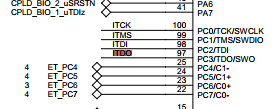
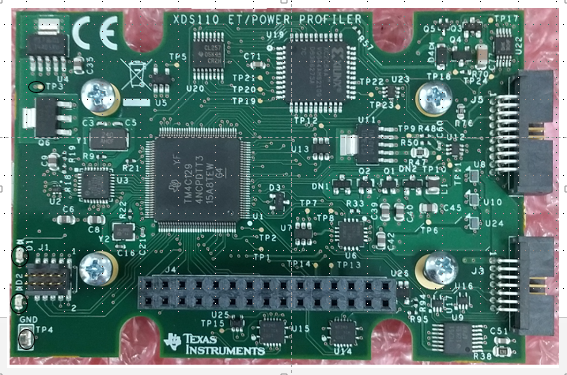
Part Number: TMDSEMU110-U
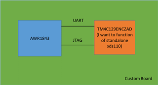
Other Parts Discussed in Thread: TM4C1294NCPDT, ALLIGATOR, TM4C129ENCZAD, AWR1843

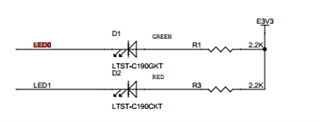
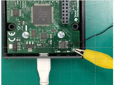
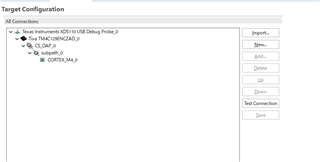
Hello, when the TMDSEMU110-U was connected via USB, the D1 part stopped glowing (probably the power supply stopped turning on).

Do you have any workaround?
By the way, I used xdsdfu.exe to switch modes until the last minute, but is that related?

  • Not sure why D1 is not lighting up, but has the TMDSEMU110-U debug probe stop functioning? Can you still see it in the Windows device manager? Can it still connect to a target device? You can also try to re-flash the debug probe if you like. Instructions given below.

    https://software-dl.ti.com/ccs/esd/documents/xdsdebugprobes/emu_xds110.html

  • As of yesterday, Device Manager disappeared.

    So I was worried about it, and when I checked it, the D1 didn't light up, so I think it didn't turn on.

    Is there any reason why it won't turn on?
    Does TI provide support such as repair for this product?

  • Based on your description, it would appear the debug probe is no longer functional. There are a few additional steps you could take to verify:

    1. Try the "Recovering a bricked XDS110 without JTAG" steps given in the document below.

    C:\ti\ccs1110\ccs\ccs_base\common\uscif\xds110\XDS110SupportReadMe.pdf  (your path may be different if you are using a different CCS version or install directory)

    2. You could try to flash the XDS110 with an XDS100v2 or XDS200 debug probe, if you have one. Some folks tried that in the thread below.

    https://e2e.ti.com/support/microcontrollers/arm-based-microcontrollers-group/arm-based-microcontrollers/f/arm-based-microcontrollers-forum/974882/tmdsemu110-u-tmdsemu110-u

    There is no option to return the probe for repair, but there is an RMA option. For that we'd need more information as to the condition of the probe at purchase (i.e. was it defective when received).

  • There also some troubleshoot steps given below which you may want to review.

    https://software-dl.ti.com/ccs/esd/documents/xdsdebugprobes/emu_xds110.html

    Also, try a different USB cable to be sure the cable is not the issue.

  • Hi, thanks for your reply.

    I still have some doubts about trying all the methods, so I will talk about it.

    Current state of my TMDSEMU110-U
    DS1 does not light up when powered via USB cable.
    (It seems that the power is not turned on in the first place.)

    what i tried
    1. Try changing the USB cable
    2. Change the location of the computer's USB connection

    In these two, the DS1 did not shine in the first place.

    what remains in doubt
    Q1.In the method you posted, it seems that you will use another debugger to write programs and input commands into the TM4C1294NCPDT inside the TMDSEMU110-U via a JTAG connection.

    Are you satisfied with that recognition?

    Q2. TMD4C1294NCPDT is the one included in TMDSEMU110-U in the XDS110 recovery work you told me, right?

    That means connecting the 97th pin among them to GND.
    So the best way to connect is to connect the JTAG pin connected to pin 97 to GND.

  • Current state of my TMDSEMU110-U
    DS1 does not light up when powered via USB cable.
    (It seems that the power is not turned on in the first place.)

    I took a look at the schematics for the probe. The LEDs are controlled by the TM4C on the board. So it could be the board is still receiving power, but the TM4C is not booting up in a correct state.

    There is an LDO on the board that supplies 3.3V. You could check the LEDs or TP3 to verify if 3.3V is present on the board.

    Q1.In the method you posted, it seems that you will use another debugger to write programs and input commands into the TM4C1294NCPDT inside the TMDSEMU110-U via a JTAG connection.

    Are you satisfied with that recognition?

    That is correct. There is a debug port for the TM4C on the board, per the forum post I pointed to.

    Q2. TMD4C1294NCPDT is the one included in TMDSEMU110-U in the XDS110 recovery work you told me, right?

    That means connecting the 97th pin among them to GND.
    So the best way to connect is to connect the JTAG pin connected to pin 97 to GND.

    Yes, that is right. The 97th pin also connects to J1 pin 6, if that is easier.

  • Hello, thank you for your detailed explanation.

    As soon as possible, I disassembled the circuit and checked it.
    (Measurement points are circled in the figure below.)

    1. As you said, I measured the voltages of TP3, LED1, and LED2 when the USB port was connected.

    ・TP3 is 3.3V
    • DS1 was 3.31 V at the anode and 1.80 V at the cathode.
    • DS2 was 3.31 V at the anode and 2.14 V at the cathode.

    I know it's probably powered by USB.

    What caught my attention here. . .
    ・When DS1 and DS2 do not light up, what is the cause?
    ・I'm also curious about the state of the TM4C1294NCPDT.
    (If you don't mind, please let me know where I can find the circuit diagram and assembly diagram for the TMDSEMU110-U.)

    2. Next, I also checked the method described in Trouble Shooting.

    In the circuit diagram below, I used the 6th pin of J1 to drop the 97th pin of TM4C to GND.
    GND is fixed with a yellow alligator clip and connected with a jumper wire.

    My device was not detected when I actually followed the steps.

    I got the following result in command prompt.

    (Command)

    ---------------------------------------------------------------------------------

    C:\ti\ccs1120\ccs\ccs_base\common\uscif\xds110>xdsdfu.exe -e


    USB Device Firmware Upgrade Utility

    Copyright (c) 2008-2019 Texas Instruments Incorporated.  All rights reserved.


    Scanning USB buses for supported XDS110 devices...


    Found 0 devices.

    ---------------------------------------------------------------------------------

    3. Lastly, you said that you would connect directly to TMDSEMU110 with another Debugger, but many Debuggers were out of stock.

    Is it possible to connect to the TMDSEMU110-U that I have with the TM4C129x evaluation board and read it?

  • When DS1 and DS2 do not light up, what is the cause?

    Looking at the LED datasheet (you can find online by searching... part number), it has a 2.1V forward voltage, so there isn't enough of a drop across the LED to light it. It looks like the TM4C is not pulling the cathode to GND.

    If you don't mind, please let me know where I can find the circuit diagram and assembly diagram for the TMDSEMU110-U.

    I'll send via private message. If you can reach out to me, please do so via forum direct message.

    My device was not detected when I actually followed the steps.

    Just to be clear, you followed these steps?

    1. Ground the JTAG TDO pin of the XDS110's Tiva CPU. This is pin 97 on the 128 pin
    device. (Check the TM4C1294NCPDT datasheet for the pin location; it is located on a
    corner and easy to access.)
    2. Unplug and re-plug the XDS110 into the host computer while the pin is grounded.
    3. The XDS110 should now be in DFU programming mode.
    4. Remove the connection to ground while the XDS110 remains powered.
    5. Use the xdsdfu utility to update the firmware as detailed above

    Is it possible to connect to the TMDSEMU110-U that I have with the TM4C129x evaluation board and read it?

    Unfortunately you need one of the debug probes I mentioned before.

  • Hello thank you.
    I'm talking about three things:

    1. LED lighting
    You say the reason the LED doesn't come on is that the TM4C isn't pulling the cathode to GND.
    What should I do about it?

    You mentioned using a forum direct message to provide the schematics, how is that possible?

    2. Procedure for device detection
    I tried your method for device detection and it still didn't work.
    (I checked the GND connection.)

    3. Alternative debugging
    I understand about this.

  • In addition, I would like to ask, is there anything other than the TMDSEMU110-U that can be used as the XDS110 Debugger?

  • 1. LED lighting
    You say the reason the LED doesn't come on is that the TM4C isn't pulling the cathode to GND.
    What should I do about it?

    The TM4C is not booting up. This is the whole point of trying to get it to boot by 1. programming it using external debug probe, or 2. tying pin 97 to GND. 

    2. Procedure for device detection
    I tried your method for device detection and it still didn't work.
    (I checked the GND connection.)

    Understood.

    is there anything other than the TMDSEMU110-U that can be used as the XDS110 Debugger?

    There may be an option to use a C2000 LaunchPad for this. What target/device are you trying to debug?

  • Hello thank you.

    1. LED lighting
    It's quick, but the LED didn't light up even after checking the procedure you posted.

    2. Procedure for device detection
    I'm glad you understand that this procedure will not bring you back.

    3. Debugger alternatives
    I want TM4C129ENCZAD to make JTAG connection and implement XDS110.

    At first, I was trying to run firmware.bin after loading bootl_loader.axf into TM4C129EN with just a USB connection to TM4C129E.
    The files are:
    (C:\ti\ccs1210\ccs\ccs_base\common\uscif\xds110)

    For that purpose, I think that a debugger that can connect CCS and TM4C129ENCZAD with JTAG is necessary.

  • I want TM4C129ENCZAD to make JTAG connection and implement XDS110.

    Ah, ok, I understand your question now. You want to program your TM4C129x evaluation board with the XDS110 firmware and use it to program the TMDSEMU110-U, correct? 

    I don't know if it's possible to run the XDS110 firmware on the TM4C129EN. You could try opening a new support thread on that topic. However, based on the thread below, it looks like you specifically need an XDS200 or XDS100v2 to program the TM4C in the TMDSEMU110-U debug probe.

    https://e2e.ti.com/support/microcontrollers/arm-based-microcontrollers-group/arm-based-microcontrollers/f/arm-based-microcontrollers-forum/974882/tmdsemu110-u-tmdsemu110-u 

    At this point it doesn't seem we'll be able to revive your TMDSEMU110-U debug probe. Can you tell me when and where you purchased this probe from? Was it functioning when you purchased it?

  • Thank you for your reply.

    you said
    'Ah, ok, I understand your question now.
    You want to program your TM4C129x evaluation board with the XDS110 firmware and use it to program the TMDSEMU110-U, correct?'

    Strictly speaking, I would like to load the program into the TM4C129ENCZAD custom board and operate it as StandAlone's XDS110.

    After running it, I would like to be able to connect the AWR1843 to a PC to write programs and use it as a debugger. (It looks like the figure below.)

    you said
    'I don't know if it's possible to run the XDS110 firmware on the TM4C129EN. You could try opening a new support thread on that topic. However, based on the thread below, it looks like you specifically need an XDS200 or XDS100v2 to program the TM4C in the TMDSEMU110-U debug probe.'

    Is that so?
    When I actually checked the Target Configuration with CCS, I was able to select TM4C129ENCZAD even with XDS110.

    you said
    'At this point it doesn't seem we'll be able to revive your TMDSEMU110-U debug probe.
    Can you tell me when and where you purchased this probe
    from?
    Was it functioning when you purchased it?'

    I understand this matter.
    I'm about to ask in a new thread if the EK-TM4C129x can be used instead of the XDS110, so I would appreciate it if you could answer.

  • I'm worried about it again, so let me ask you.

    In the JTAG wiring materials below, only the 10 kΩ resistors that pull up the 99th and 100th pins are mounted on the board inside the TMDSEMU110-U. (The rest are not implemented.)

    And it is R7 and R4 that play that role inside the TMDSEM110-U.

  • Thanks for the added information. For implementing your own XDS110 I would suggest you use as reference one of our C2000 LaunchPads or controlCARDs. Here are some examples you can use:

    https://www.ti.com/tool/LAUNCHXL-F280039C

    https://www.ti.com/tool/TMDSCNCD280039C 

    I would also highly recommend you stick with either the MSP432E401YTPDT or the TM4C1294NCPDTI3 as the host MCU. Both of these have been proven to run the firmware. If you use any other MCU, I am not sure if anybody at TI will be able to support any debug issues you may face.

  • This design was done some time ago by some folks that have moved on to other roles. I do not have the answers to these questions. 

  • Please let me know if you know anyone.

  • Thank you for your reply.

    You said
    Thanks for the added information. For implementing your own XDS110 I would suggest you use as reference one of our C2000 LaunchPads or controlCARDs. Here are some examples you can use:

    www.ti.com/.../LAUNCHXL-F280039C

    www.ti.com/.../TMDSCNCD280039C

    Thank you for your offer.
    Am I correct in understanding that 'you use as reference one of our C2000 LaunchPads or controlCARDs' should be referred to the circuit diagrams to design the board?

    You said
    I would also highly recommend you stick with either the MSP432E401YTPDT or the TM4C1294NCPDTI3 as the host MCU. Both of these have been proven to run the firmware. If you use any other MCU, I am not sure if anyone at TI will be able to support any debug issues you may face.

    Is it correct to assume that this is because the TM4C1294NCPDT is used in the internal circuit of the Debug Probe?

  • Per my understanding, you are trying to embed the XDS110 on your board. The two boards I referenced have an embedded XDS110 emulator on them. I am saying you can use those schematics as a reference for your design.

    Both the MSP432E401YTPDT and the TM4C1294NCPDTI3 are used in XDS110 designs (TMDSEMU110-U, embedded XDS110, etc.), so it is proven that the XDS110 firmware will run on these devices. 

  • Hello, I have been wondering about something I raised in this thread.Is there anything that may break down if the firmware ver is old?

    I had the internal device switched to dfu mode from the command and then boot_loader.bin from the command and then firmware_3.0.0.13.bin.
    The hierarchy is as follows.
    C:\ti\ccs_base\common\uscif\xds110

    switch command
    xdsdfu.exe -m
    xdsdfu.exe -b boot_loader.bin -r

    USB Device Firmware Upgrade Utility
    Copyright (c) 2008-2019 Texas Instruments Incorporated.

    Replacing the bootloader may render the XDS110 unusable.
    Do you want to continue (Y/N)?Y
    Scanning USB buses for supported XDS110 devices...

    Downloading boot_loader.bin to device...

    xdsdfu.exe -f firmware_3.0.0.13.bin -r

    USB Device Firmware Upgrade Utility

    After this was over, I immediately turned off the power and then turned it on again.

    By doing this the Debugger no longer sees the port in Device Manager.

    Could this be the cause of the failure?
    Also, is there a way to check the cause of the failure?
    If so, could you tell me how to solve it? (If you have any materials, please teach me.)

  • Let me see if I can get this ticket transferred to somebody that can answer your questions. 

  • Gus - some of this topic was discussed in depth in the below post:

    https://e2e.ti.com/support/microcontrollers/arm-based-microcontrollers-group/arm-based-microcontrollers/f/arm-based-microcontrollers-forum/1185252/tm4c129enczad-what-to-do-when-the-device-is-not-found

    One thing to keep in mind:

    Both the MSP432E401YTPDT and the TM4C1294NCPDTI3 are used in XDS110 designs (TMDSEMU110-U, embedded XDS110, etc.), so it is proven that the XDS110 firmware will run on these devices. 

    Kanematu-san is using a TM4C129ENCZAD, which is NOT pin-out compatible to the devices you mentioned above. CCS engineers are not certain that the XDS110 firmware will run successfully on the TM4C129ENCZAD.