Part Number: TM4C123GH6PM
Hello,
Currently I am obtaining 2 independent PWM signals from pin PB6 and PB7 using single PWM generator, such as:
MAP_SysCtlPWMClockSet(SYSCTL_PWMDIV_8);
ui32PWMClock = ui32SysClkFreq / PWM_DIV;
ui32Load = (ui32PWMClock / PWM_FRQ) - 1;
MAP_SysCtlPeripheralEnable(SYSCTL_PERIPH_PWM0);
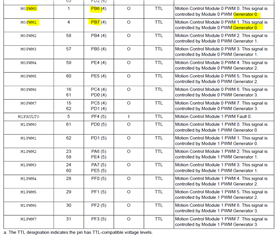
MAP_GPIOPinConfigure(GPIO_PB6_M0PWM0);
MAP_GPIOPinConfigure(GPIO_PB7_M0PWM1);
MAP_GPIOPinTypePWM(GPIO_PORTB_BASE, GPIO_PIN_6);
MAP_GPIOPinTypePWM(GPIO_PORTB_BASE, GPIO_PIN_7);
MAP_PWMGenConfigure(PWM0_BASE, PWM_GEN_0, PWM_GEN_MODE_UP_DOWN | PWM_GEN_MODE_NO_SYNC);
MAP_PWMGenPeriodSet(PWM0_BASE, PWM_GEN_0, ui32Load);
MAP_PWMGenEnable(PWM0_BASE, PWM_GEN_0);
MAP_PWMOutputState(PWM0_BASE, PWM_OUT_0_BIT | PWM_OUT_1_BIT, true);
Right now, I am using count up down strategy to obtain 2 different PWM signals, from single generator.
Can I use different PWM generators on pin PB6 and PB7? So I can take advantage of pwm sync, and other features? Or would I have to rewire my board and use a different pin for the second pwm generator.
Best Regards,
Can