This thread has been locked.

If you have a related question, please click the "Ask a related question" button in the top right corner. The newly created question will be automatically linked to this question.

TM4C129DNCPDT: Unable to programmed microcontroller

Part Number: TM4C129DNCPDT
Other Parts Discussed in Thread: UNIFLASH, TCA9555, EK-TM4C1294XL

Hi,

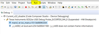
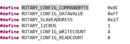
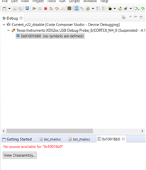
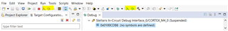
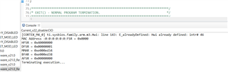
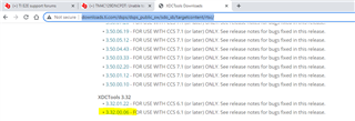
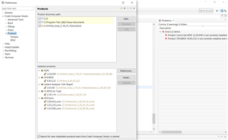
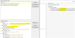
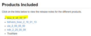
I’m trying to load a reference running code of my project in the new board but it is not working, I can’t share my project’s code here as it is proprietary so need to contact someone directly to help me debug this issue.

Thanks,

Kiranjit 

  • Hi, 

      Does the reference code run on the LaunchPad?

  • Hi Charles,

    Example codes are running on Launchpad but reference code is not working.

    Please share your comments or suggestions.

    Thanks,

    Kiranjit 

  • Hi Kiranjit,

    Example codes are running on Launchpad but reference code is not working.

     I'm a bit confused. What is the difference between example code and reference code?

    Which example code are you referring to?

    Is reference code your own code?

    Does the reference code work on LaunchPad?

    Does the example code work on your own board?

    Please answer above questions so we can isolate the problem to see if it related to the hardware or software. 

  • Hi Charles,

    What is the difference between example code and reference code?

    Which example code are you referring to?

    Is reference code your own code?

    >>> The example code is one of the example projects that come with tirtos. The reference code is our already working project code. Example codes like giving some output through I2C protocol or glowing an LED etc.

    Does the reference code work on LaunchPad?

    Does the example code work on your own board?

    >>> We have a reference board on which our reference working project code is running perfectly fine. But on our newly designed prototype board, the reference working project code is not running. The example code works on our new board.

    Another point is that when I'm commenting all the initializations in the reference working project and only glowing an LED, it is working in DEBUG MODE on the new board but not working when programming through CCS uniflash.

    Kindly help clarify the things.

    Best Regards,

    Kiran

  • >>> We have a reference board on which our reference working project code is running perfectly fine. But on our newly designed prototype board, the reference working project code is not running. The example code works on our new board.

    Here are my comments:

    - What is the difference between the reference board and the newly designed proto board? If the reference code works on the reference board but not the proto board then it suggests some hardware issue. 

    -The example code maybe simple enough that it only turns on a LED and some simple I2C transactions. The example code may not reveal the hardware difference that is preventing the proto board from working when running the reference code. 

     - What is the major difference between the reference code and the example code? I suppose your reference code has much more than just turning on LED and I2C transactions. Focus on the differences between the reference code and the example code. 

  • Hi Charles,

    Can you help me with my last point?

    Another point is that when I'm commenting all the initializations in the reference working project and only glowing an LED, it is working in DEBUG MODE on the new board but not working when programming through CCS uniflash.

    Thanks,

    Kiranjit

  • Another point is that when I'm commenting all the initializations in the reference working project and only glowing an LED, it is working in DEBUG MODE on the new board but not working when programming through CCS uniflash.

    Do you see the same behavior when running on the LaunchPad and your reference board after you commenting out all the initialization in the reference?

  • Yes the behavior is same on Launchpad as well as my new prototype board

  • What initializations did you remove? 

  • Hi Charles,

    Please see the following code snippet:


    //Board_initGeneral();
    //Board_initGPIO();
    // Board_initPWM();
    //Board_initUART();
    //Board_initI2C();
    // Board_initSPI();
    //UARTUtils_systemInit(0);
    //Board_initWatchdog();
    // PinoutSet();

    /* System Clock frequency Set to 120MHz */
    System_printf("clock %d", SysCtlClockFreqSet((SYSCTL_XTAL_25MHZ |
    SYSCTL_OSC_MAIN | SYSCTL_USE_PLL |
    SYSCTL_CFG_VCO_480), 120000000));
    SysCtlMOSCConfigSet(SYSCTL_MOSC_HIGHFREQ);

    //StatusLEDConfig();

    SysCtlPeripheralEnable(SYSCTL_PERIPH_GPIOG);

    // Check if the peripheral access is enabled.
    //
    while(!SysCtlPeripheralReady(SYSCTL_PERIPH_GPIOG))
    {
    }

    //
    // Enable the GPIO pin for the (PG3). Set the direction as output, and
    // enable the GPIO pin for digital function.
    //
    GPIOPinTypeGPIOOutput(GPIO_PORTG_BASE, GPIO_PIN_3);

    GPIOPinWrite(GPIO_PORTG_BASE, GPIO_PIN_3, GPIO_PIN_3);

    The commented ones are the removed initializations.

    Best Regards,

    Kiranjit

  • Are you using TI-RTOS? I see you use System_printf. 

    If you are using TI-RTOS, it will initialize the system clock already.  See below. 

    There is no need to call SysCtlClockFreqSet. I also don't see the reason to call 

    SysCtlMOSCConfigSet(SYSCTL_MOSC_HIGHFREQ); Why don't you remove these two lines?

    Did you also comment out the BIOS_start()?

  • Hi Charles,

    Yes we're using TI-RTOS. I commented SysCtlClockFreqSet and SysCtlCMOSConfigSet(SYSCTL_MOSC_HIGHFREQ) and also BIOS_start() but still I'm having the same issue that with Debug method it is working but not with programming through CCS Uniflash utility.

    Can you suggest the reason?

    Best Regards,

    Kiranjit 

  • Hi,

      I cannot reproduce your issue. I import the pwmled example from CCS Resource Explorer as a starting point. I then remove most of the code and paste your code. See below. I rebuild the modified project using CCS. I change from PG3 to PN0 pin in order to see LED on the LaunchPad board. I load the program in CCS and run it. I can see the LED turned on. Next, I load the same .out file using Uniflash version 5.3.1. It is loaded successfully, and as soon as it is run, I can also see the LED turned on. I can reset the device and after reset, the LED will turn on with no issue. I will suggest you compare your code with the below. You can also import the pwmled example from Resource Explorer. 

    /*
     *  ======== pwmled.c ========
     */
    /* XDCtools Header files */
    #include <xdc/std.h>
    #include <xdc/runtime/System.h>
    
    /* BIOS Header files */
    #include <ti/sysbios/BIOS.h>
    #include <ti/sysbios/knl/Task.h>
    
    /* TI-RTOS Header files */
    #include <ti/drivers/GPIO.h>
    #include <ti/drivers/PWM.h>
    
    //------------------------------------------
    // TivaWare Header Files
    //------------------------------------------
    #include <stdint.h>
    #include <stdbool.h>
    
    #include "inc/hw_types.h"
    #include "inc/hw_memmap.h"
    #include "driverlib/pwm.h"
    
    /* Example/Board Header files */
    #include "Board.h"
    
    //------------------------------------------
    // TivaWare Header Files
    //------------------------------------------
    #include <stdint.h>
    #include <stdbool.h>
    
    #include "inc/hw_types.h"
    #include "inc/hw_memmap.h"
    #include "driverlib/sysctl.h"
    #include "driverlib/gpio.h"
    #include "inc/hw_ints.h"
    #include "driverlib/interrupt.h"
    #include "driverlib/timer.h"
    
    /*
     *  ======== pwmLEDFxn ========
     *  Task periodically increments the PWM duty for the on board LED.
     */
    
    
    /*
     *  ======== main ========
     */
    int main(void)
    {
        //Board_initGeneral();
        //Board_initGPIO();
        // Board_initPWM();
        //Board_initUART();
        //Board_initI2C();
        // Board_initSPI();
        //UARTUtils_systemInit(0);
        //Board_initWatchdog();
        // PinoutSet();
    
        /* System Clock frequency Set to 120MHz */
        System_printf("clock %d", SysCtlClockFreqSet((SYSCTL_XTAL_25MHZ |
        SYSCTL_OSC_MAIN | SYSCTL_USE_PLL |
        SYSCTL_CFG_VCO_480), 120000000));
        SysCtlMOSCConfigSet(SYSCTL_MOSC_HIGHFREQ);
    
        //StatusLEDConfig();
    
        SysCtlPeripheralEnable(SYSCTL_PERIPH_GPION);
    
        // Check if the peripheral access is enabled.
        //
        while(!SysCtlPeripheralReady(SYSCTL_PERIPH_GPION))
        {
        }
    
        //
        // Enable the GPIO pin for the (PG3). Set the direction as output, and
        // enable the GPIO pin for digital function.
        //
        GPIOPinTypeGPIOOutput(GPIO_PORTN_BASE, GPIO_PIN_0);
    
        GPIOPinWrite(GPIO_PORTN_BASE, GPIO_PIN_0, GPIO_PIN_0);
    
        /* Start BIOS */
        BIOS_start();
    
        return (0);
    }

    but not with programming through CCS Uniflash utility.

      Maybe I'm not clear what you meant by not working with CCS Uniflash. Can you clarify a few questions. 

      - Can you program the code to the flash using CCS Uniflash successfully?

      - What version of Uniflash do you have? I use v5.3.1/ Have you tried other versions?

      - When you said not working, what exactly does that mean? Do you see the LED turned ON. Can you try my code above?


  • Hi Charles,

    Can you program the code to the flash using CCS Uniflash successfully?

    I can successfully program the code using CCS Uniflash.

      - What version of Uniflash do you have? I use v5.3.1/ Have you tried other versions?

    I have uniflash 3.4,I'll try other version and update you.

    When you said not working, what exactly does that mean? Do you see the LED turned ON. Can you try my code above?


    If I write a separate code then it works but if I comment everything in my reference working code and only, say I glow an LED then it doesn't work when programming through uniflash but works when running in debug mode.

    Hope things are clear now.

    Can you help in this? Can a meeting be arranged?

    Best Regards,

    Kiran

  • Hi,

      Can you post your entire program, not just a snippet of the code? 

  • Hi Charles,

    Due to IP issues, i am not able to post entire code.

    Thanks,

    Kiran 

  • Hi,

      You can add me as a friend and send me the file privately. 

  • Hi Charles,

    I will share after our internal discussion with team.

    It would be better if we could arrange a meeting so that you can see the issue in real time. Please try for a meeting. 

    In the mean time, please suggest some troubleshooting steps for debugging issue.

    why my code is running in debug mode only?

    Thanks,

    Kiran

  • Hi,

      What is the reason why you want to remove the initialization code? 

      When you load your reference code with the initialization using Uniflash, does it work? 

      When you load your reference code without the initialization using Uniflash, does it work? 

      Please clarify what you mean that it is working in debug mode? Do you mean loading the reference code in CCS and then run the code while the debugger is connected?

      When you load your reference code with the initialization using CCS in debug mode, does it work? 

      When you load your reference code without the initialization using CCS in debug mode, does it work? 

      Can you run the code while the debugger is connected but select 'Free Run'.  See below. This is supposed to disengage the debugger when running the program. Can you repeat the failure? 


      I don't know yet why would it make a difference between running the code when the debugger is connected vs. not connected? 

      Finally, our support model is through e2e. 


  • Hi Charles,

      What is the reason why you want to remove the initialization code? 

    I removed the initialization just to verify what is blocking my code.

      When you load your reference code with the initialization using Uniflash, does it work? 

      When you load your reference code without the initialization using Uniflash, does it work? 

    My reference code is not working with Uniflash (with or without initialization) on my prototype board,

    Please clarify what you mean that it is working in debug mode? Do you mean loading the reference code in CCS and then run the code while the debugger is connected?

    Yes, that is what I mean, running the code while debugger is connected.

    When you load your reference code with the initialization using CCS in debug mode, does it work? 

      When you load your reference code without the initialization using CCS in debug mode, does it work?

    The reference code is working with CCS in Debug mode (with and without initialization).

    Can you run the code while the debugger is connected but select 'Free Run'.  See below. This is supposed to disengage the debugger when running the program. Can you repeat the failure?

    I am not getting the option 'Free Run' option on right-clicking. How do I find the 'Free Run' option? See below

    I pressed Ctrl + F8 and I get the following:

    Any suggestions for this behaviour?

    Best Regards,

    Kiranjit

  • Hi,

    While debugging I(the original reference code without any modifications) I found the following (In BIOS--> Scan for Errors)

  • I am not getting the option 'Free Run' option on right-clicking. How do I find the 'Free Run' option? See below

    I pressed Ctrl + F8 and I get the following:

    Please first click the 'Run' pulldown menu and you should see the 'Free Run' that I showed earlier. 

    I don't know how complex your project is. I can't seem to understand what is causing your problem. This is what I will suggest. 

    1. Start with a known working program. For example, you can choose one of the TI-RTOS examples. 

    2. Add your own code piece by piece. What I mean piece by piece is more like one functionality at a time. For example, add a UART function. Rebuild the project and see if you are running into any issues in either debug mode or loading the program through Uniflash and then run. 

    3. If there is no issue in the above step, add the next functionality to your code. For example, add I2C. Do the same as in step 2. If there is no issue loading the code through Uniflash and running the code then continue with the next functionality. 

     I hope by doing a small step at a time will help troubleshoot why it is not working for your reference code on your new board board. 

     Below is a comment you made before which makes me really confused. You said that your reference code was working on a reference board perfectly fine at one point of time but not on your new board. What is the difference between your reference board and your new board?

    >>> We have a reference board on which our reference working project code is running perfectly fine. But on our newly designed prototype board, the reference working project code is not running. The example code works on our new board.

  • Hi Charles ,

    I will try the above steps as you said but the reference code is quite complex with modbus communication through fiber channels, digital and analog I/Os, protocols used include ethernet,dma,uart,i2c,spi and several other things with different events and semaphores being called and I'm only supposed to modify some portion of it.

    We load 4 bin files in 4 different sectors of the flash memory, i.e. Boot Code, Current Image, Golden Image and Common Data(Non Volatile Data)

    The reference board is a working board on which my reference code is working. After modifying few portions in the schematic for added functionality, a new prototype board has been designed and the existing reference code does not work on that prototype board.

    Hope that clears your question.

    Thanks,

    Kiran

  • Hi Kiran,

    fter modifying few portions in the schematic for added functionality, a new prototype board has been designed and the existing reference code does not work on that prototype board.

      Do you know what exactly was added or changed to the new board compared to the reference board. 

      Just to make sure your reference code still works on the reference board, can you rerun to confirm this is still the case. This will help you isolate the problem on how the hardware changes on the new proto board are affecting the reference code. 

  • Hi Charles,

    Do you know what exactly was added or changed to the new board compared to the reference board. 

    >> Yes, i worked with electrical person during schematic design. Added one RJ45 port connection with exiting fiber port and combined rotatory switch connection and LED connection with single IO expander(TCA9555) earlier it was using separate IO expander (TCA955).

    Below is one snippet of IO expander code where it was interfaced with switch.

    Can you please explain significance of commandbyte value (0X8C)? 

    Just to make sure your reference code still works on the reference board

    >> Yes it is working on reference board as mentioned earlier also.

    how the hardware changes on the new proto board are affecting the reference code

    >> Hardware changes are working with examples codes(i2c and LED blinking) but not with reference code.

    Examples codes are working so that we can conclude that hardware interface with controller is fine. 

    I will try your suggested steps.

    Thanks,

    Kiran

  • Hi Kiran,

      First of all, I have yet to grasp what works and what does not. Please fill out the below table. I fill out what I know so far. If I have misunderstanding on what works and what does not, please correct. 

      LaunchPad Reference board New proto board
    example code loaded through CCS Debug Work Work Work
    reference code loaded through CCS Debug   Work Work
    example code loaded through Uniflash      
    reference code loaded through Uniflash   Work Not Work

    Can you please explain significance of commandbyte value (0X8C)? 

    Please understand that I can only answer questions related to MCU, not TCA955. You will need to consult the support team for TCA9555. 

     When you say the reference code loaded through Uniflash does not work, have you tried to connect with the debugger afterward and find out where the code is stuck at? You just need to load the symbol and you should be able to find out what the code is doing. 

  • Hi Charles,

    Please find the table filled below:

      LaunchPad Reference board New proto board
    example code loaded through CCS Debug working working working
    reference code loaded through CCS Debug working working working
    example code loaded through CCS Uniflash working working working
    reference code loaded through CCS Uniflash not working not working working
    modifications in reference code loaded through CCS Uniflash not working not working not working
    modifications in reference code loaded through CCS Debug working working working

    When you say the reference code loaded through Uniflash does not work, have you tried to connect with the debugger afterward and find out where the code is stuck at? You just need to load the symbol and you should be able to find out what the code is doing. 

    How do I load the symbol?

  • How do I load the symbol?

    See below and provide your .out file. CCS will extract the symbols. You will need to do the debugging yourself. 

      LaunchPad Reference board New proto board
    example code loaded through CCS Debug working working working
    reference code loaded through CCS Debug working working working
    example code loaded through CCS Uniflash working working working
    reference code loaded through CCS Uniflash not working not working working
    modifications in reference code loaded through CCS Uniflash not working not working not working
    modifications in reference code loaded through CCS Debug working working working

    Are you sure the  reference code is working in the New proto board but not in Reference board and LaunchPad? Can you check each field again?

    It is becoming too hard for me to grasp what is working and not. There are already 18 combinations. This is not even including the initialization code being commented out or not. I think this is what I will suggest.

    1. Load your reference code or modified reference code through Uniflash.

    2. Connect to the target through CCS. 

    3. Load the symbols as explained earlier.

    4. Do a reset. Got Run->Reset->System Reset.

    5. Run and do single step at wherever you are stuck. 

    Your system seems complicated enough that I don't really know how to help from my side other than the above troubleshooting suggestions. 

  • Hi Charles,

    Can you run the code while the debugger is connected but select 'Free Run'.  See below. This is supposed to disengage the debugger when running the program. Can you repeat the failure? 

    I tried the 'Free Run' option and the code is not running even in that mode.

    Are you sure the  reference code is working in the New proto board but not in Reference board and LaunchPad? Can you check each field again?

    Sorry for the incorrection, please find the corrected table below

    Task Performed  LaunchPad Reference board New proto board
    example code loaded through CCS Debug working working working
    reference code loaded through CCS Debug unable to check due to lack of hardware support working not working
    example code loaded through CCS Uniflash working working working
    reference code loaded through CCS Uniflash unable to check due to lack of hardware support working not working
    modifications in reference code loaded through CCS Uniflash not working not working not working
    modifications in reference code loaded through CCS Debug working working working

    See below and provide your .out file. CCS will extract the symbols. You will need to do the debugging yourself. 

    In the 'Load Symbols' option, how do I proceed after the following step?

    4. Do a reset. Got Run->Reset->System Reset.

    After I do Reset -> System Reset, I get the following error

    5. Run and do single step at wherever you are stuck

    How to run single step while debugging?

    Thanks,

    Kiran

  • Hi,

    This is not even including the initialization code being commented out or not.

    In the table shared, the modifications include the initialization code being commented

  • Task Performed  LaunchPad Reference board New proto board
    example code loaded through CCS Debug working working working
    reference code loaded through CCS Debug unable to check due to lack of hardware support working not working
    example code loaded through CCS Uniflash working working working
    reference code loaded through CCS Uniflash unable to check due to lack of hardware support working not working
    modifications in reference code loaded through CCS Uniflash not working not working not working
    modifications in reference code loaded through CCS Debug working working working

    You have 

    modifications in reference code loaded through CCS Uniflash not working not working not working

    I will suggest you debug your modified reference code through CCS Uniflash since we know your reference board is a working board. We can rule out the hardware. 

    n the 'Load Symbols' option, how do I proceed after the following step?

    You just specify the .out file and select Load Symobol and click OK. Why don't you start with a very basic non-TI-RTOS example like blinky or hello. Load the blinky through Uniflash and then connect the debugger. Do the load symbol next and you will see all the code for debug. 

    4. Do a reset. Got Run->Reset->System Reset.

    After I do Reset -> System Reset, I get the following error

    The reason is that the address 0x10016B0 is a ROM address. These are driver library functions stored in ROM and there is no symbols for them. 

    How to run single step while debugging?

    See below, Click these icons to single-step source code or the assembly code.  I think you need to learn how to use CCS or any debugger first. 

  • Hi Charles,

    Thanks for your response!

    I will respond you soon for above comments.

    Please share your feedbacks on below point:

    • Pin number 6 , 74 & 104 are pulled up by default when signals are not there. These are newly added interrupt signals and not defined in reference code. It will affect the functionality of microcontroller?

    Thanks,

    Kiran

  • Hi,

    • Pin number 6 , 74 & 104 are pulled up by default when signals are not there. These are newly added interrupt signals and not defined in reference code. It will affect the functionality of microcontroller?

    pin 6 - PQ1

    pin 74 - PM4

    pin 104 - PP3

    Are you using these pins as GPIO inputs for generating interrupts?

    Did yo first enable these ports for PortQ, PortM and PortP before using them? If you don't first enable them you can get a bus fault. However, this does not seem to be the case because you said your modified reference code will run in debug mode. Anyway, you should check that they are enabled first. 

  • Hi,

    The hardware for these pins is not yet connected and they're pulled up by default so enabling/disabling these ports shouldn't affect the other functionality according to me

  • Hi,

      Whether these pins are connected is one thing and if your code are accessing these pins is another thing. For example, if you have a pin in Port XYZ that is not connected but your code tries to access the registers for this Port XYZ without enabling the port then you will get a bus fault. This is not to say your current code has this issue. It is just to clarify that you can still get a fault even the pin is not connected at the board level.  

  • Hi Charles,

    I'm not using those pins in the code,just checking the code step by step by commenting everything first and then turning on one thing at a time(tough it's still working in the Debug mode only).

    Could you check the following code snippet?

    #ifdef MAC_ADDR_PRINT
    uint8_t i, macAddress[6];
    uint32_t ui32User0, ui32User1;

    FlashUserGet(&ui32User0, &ui32User1);
    macAddress[0] = ((ui32User0 >> 0) & 0xff);
    macAddress[1] = ((ui32User0 >> 8) & 0xff);
    macAddress[2] = ((ui32User0 >> 16) & 0xff);
    macAddress[3] = ((ui32User1 >> 0) & 0xff);
    macAddress[4] = ((ui32User1 >> 8) & 0xff);
    macAddress[5] = ((ui32User1 >> 16) & 0xff);
    System_printf("MAC Address :");
    for(i = 0; i < 6; i++)
    System_printf("%x:",macAddress[i]);
    #endif
    System_flush();

    /* Init EMAC */
    Board_initEMAC();

    /* Error Block Handler */
    Error_init(&eb);

    // Start BIOS
    BIOS_start();

    return (0);

    In the above code portion, if I uncomment the line,BIOS_start(),then my code doesn't reach the breakpoint at return(0) and terminates (see following screenshot)

    If BIOS_start() is commented,then the breakpoint at return(0) reaches. Please guide why this should happen.

    Best Regards,

    Kiran

  • If BIOS_start() is commented,then the breakpoint at return(0) reaches

    This is expected. If you don't call BIOS_start() then the code will just exit the function main().  If you call BIOS_start(), the TI-RTOS handles the scheduling and will never reach return(). Bear in mind that main() is also a function. After it executes the last line of code it has to go somewhere. It then goes to exit(). 

    See example here. 

    https://www.tutorialspoint.com/c_standard_library/c_function_exit.htm

  • Hi Charles,

    Thanks for your response!!

    I am also working on validation of PHY interface with microcontroller using enet_tcpecho_server example code with launchpad.

    I am able to get IP address through tera term but flailed in socket test, also not able to connect target using ROV.

    Below image for your reference.


    Please share your feedback to validate this code on launchpad.

    Thanks,

    Kiran

    //*****************************************************************************
    //
    // enet_tcp_echo_server.c - Sample Echo Server Application using lwIP.
    //
    // Copyright (c) 2019-2020 Texas Instruments Incorporated.  All rights reserved.
    // Software License Agreement
    // 
    // Texas Instruments (TI) is supplying this software for use solely and
    // exclusively on TI's microcontroller products. The software is owned by
    // TI and/or its suppliers, and is protected under applicable copyright
    // laws. You may not combine this software with "viral" open-source
    // software in order to form a larger program.
    // 
    // THIS SOFTWARE IS PROVIDED "AS IS" AND WITH ALL FAULTS.
    // NO WARRANTIES, WHETHER EXPRESS, IMPLIED OR STATUTORY, INCLUDING, BUT
    // NOT LIMITED TO, IMPLIED WARRANTIES OF MERCHANTABILITY AND FITNESS FOR
    // A PARTICULAR PURPOSE APPLY TO THIS SOFTWARE. TI SHALL NOT, UNDER ANY
    // CIRCUMSTANCES, BE LIABLE FOR SPECIAL, INCIDENTAL, OR CONSEQUENTIAL
    // DAMAGES, FOR ANY REASON WHATSOEVER.
    // 
    // This is part of revision 2.2.0.295 of the EK-TM4C1294XL Firmware Package.
    //
    //*****************************************************************************
    
    #include <stdbool.h>
    #include <stdint.h>
    #include <string.h>
    #include "inc/hw_ints.h"
    #include "inc/hw_memmap.h"
    #include "driverlib/debug.h"
    #include "driverlib/flash.h"
    #include "driverlib/gpio.h"
    #include "driverlib/interrupt.h"
    #include "driverlib/rom.h"
    #include "driverlib/rom_map.h"
    #include "driverlib/sysctl.h"
    #include "driverlib/systick.h"
    #include "drivers/pinout.h"
    #include "lwip/tcp.h"
    #include "utils/locator.h"
    #include "utils/lwiplib.h"
    #include "utils/uartstdio.h"
    #include "utils/ustdlib.h"
    
    //*****************************************************************************
    //
    //! \addtogroup example_list
    //! <h1>Ethernet TCP Echo Server (enet_tcp_echo_server)</h1>
    //!
    //! This example application demonstrates the operation of the TM4C129x
    //! Ethernet controller using the lwIP TCP/IP Stack.  DHCP is used to obtain
    //! an Ethernet address.  If DHCP times out without obtaining an address,
    //! AutoIP will be used to obtain a link-local address.  The address that is
    //! selected will be shown on the UART.  The application echoes back the data
    //! received from the client.
    //!
    //! UART0, connected to the Virtual Serial Port and running at 115,200, 8-N-1,
    //! is used to display messages from this application.
    //!
    //! For additional details on lwIP, refer to the lwIP web page at:
    //! http://savannah.nongnu.org/projects/lwip/
    //
    //*****************************************************************************
    
    //*****************************************************************************
    //
    // Defines for setting up the system clock.
    //
    //*****************************************************************************
    #define SYSTICKHZ               100
    #define SYSTICKMS               (1000 / SYSTICKHZ)
    
    //*****************************************************************************
    //
    // Interrupt priority definitions.  The top 3 bits of these values are
    // significant with lower values indicating higher priority interrupts.
    //
    //*****************************************************************************
    #define SYSTICK_INT_PRIORITY    0x80
    #define ETHERNET_INT_PRIORITY   0xC0
    
    //*****************************************************************************
    //
    // The variable g_ui32SysClock contains the system clock frequency in Hz.
    //
    //*****************************************************************************
    uint32_t g_ui32SysClock;
    
    //*****************************************************************************
    //
    // The current IP address.
    //
    //*****************************************************************************
    uint32_t g_ui32IPAddress;
    
    //*****************************************************************************
    //
    // Global counter to keep track the duration the connection has been idle.
    //
    //*****************************************************************************
    uint32_t g_ui32tcpPollTick = 0;
    
    //*****************************************************************************
    //
    // Volatile global flag to manage LED blinking, since it is used in interrupt
    // and main application.  The LED blinks at the rate of SYSTICKHZ.
    //
    //*****************************************************************************
    volatile bool g_bLED;
    
    //*****************************************************************************
    //
    // This is the buffer to receive the TCP payload.  Data in this buffer is then
    // processed before echoing back to the host.
    //
    //*****************************************************************************
    char g_pctcpBuffer[4096] = {0};
    
    //*****************************************************************************
    //
    // The error routine that is called if the driver library encounters an error.
    //
    //*****************************************************************************
    #ifdef DEBUG
    void
    __error__(char *pcFilename, uint32_t ui32Line)
    {
    }
    #endif
    
    //*****************************************************************************
    //
    // Display an lwIP type IP Address.
    //
    //*****************************************************************************
    void
    DisplayIPAddress(uint32_t ui32Addr)
    {
        char pcBuf[16];
    
        //
        // Convert the IP Address into a string.
        //
        usprintf(pcBuf, "%d.%d.%d.%d", ui32Addr & 0xff, (ui32Addr >> 8) & 0xff,
                (ui32Addr >> 16) & 0xff, (ui32Addr >> 24) & 0xff);
    
        //
        // Display the string.
        //
        UARTprintf(pcBuf);
    }
    
    //*****************************************************************************
    //
    // Required by lwIP library to support any host-related timer functions.
    //
    //*****************************************************************************
    void
    lwIPHostTimerHandler(void)
    {
        uint32_t ui32NewIPAddress;
    
        //
        // Get the current IP address.
        //
        ui32NewIPAddress = lwIPLocalIPAddrGet();
    
        //
        // See if the IP address has changed.
        //
        if(ui32NewIPAddress != g_ui32IPAddress)
        {
            //
            // See if there is an IP address assigned.
            //
            if(ui32NewIPAddress == 0xffffffff)
            {
                //
                // Indicate that there is no link.
                //
                UARTprintf("Waiting for link.\n");
            }
            else if(ui32NewIPAddress == 0)
            {
                //
                // There is no IP address, so indicate that the DHCP process is
                // running.
                //
                UARTprintf("Waiting for IP address.\n");
            }
            else
            {
                //
                // Display the new IP address.
                //
                UARTprintf("IP Address: ");
                DisplayIPAddress(ui32NewIPAddress);
                UARTprintf("\nEcho Server is ready.\n");
            }
    
            //
            // Save the new IP address.
            //
            g_ui32IPAddress = ui32NewIPAddress;
        }
    
        //
        // If there is not an IP address.
        //
        if((ui32NewIPAddress == 0) || (ui32NewIPAddress == 0xffffffff))
        {
            //
            // Do nothing and keep waiting.
            //
        }
    }
    
    //*****************************************************************************
    //
    // The interrupt handler for the SysTick interrupt.
    //
    //*****************************************************************************
    void
    SysTickIntHandler(void)
    {
        //
        // Call the lwIP timer handler.
        //
        lwIPTimer(SYSTICKMS);
    
        //
        // Tell the application to change the state of the LED (in other words
        // blink).
        //
        g_bLED = true;
    }
    
    //*****************************************************************************
    //
    // Callback function to close the connection.
    //
    //*****************************************************************************
    static void
    close_conn (struct tcp_pcb *pcb)
    {
        //
        // NULL will be passed to all other callback functions.
        //
        tcp_arg(pcb, NULL);
        //
        // NULL callback for the PCB when data is sent.
        //
        tcp_sent(pcb, NULL);
        //
        // NULL callback for the PCB when data is received.
        //
        tcp_recv(pcb, NULL);
        //
        // Closes the connection held by the PCB.
        //
        tcp_close(pcb);
    }
    
    //*****************************************************************************
    //
    // Callback function to indicate the number of bytes that were acknowledged by
    // last acknowledgment.
    //
    //*****************************************************************************
    static err_t
    echo_sent(void *arg, struct tcp_pcb *tpcb, u16_t len)
    {
      LWIP_UNUSED_ARG(arg);
    
      //
      // Print a message indicating the number of bytes that has been acknowledged
      // by the remote host.
      //
      UARTprintf("\rBytes acknowledged by the remote host:%4d", len);
    
      return ERR_OK;
    }
    
    //*****************************************************************************
    //
    // Callback function to process the received data from the client.
    //
    //*****************************************************************************
    static err_t
    echo_recv( void *arg, struct tcp_pcb *pcb, struct pbuf *p, err_t err)
    {
        uint32_t ui32index;
        uint32_t ui32len;
        char *pcpayLoad;
        char pcheaderMsg[45];
        uint32_t ui32statuslen;
    
        //
        // Clear the Idle time counter.
        //
        g_ui32tcpPollTick = 0;
    
        if (err == ERR_OK && p != NULL)
        {
            //
            // tcp_recved must be called when the application has processed the
            // data and is prepared to receive more.
            //
            tcp_recved(pcb, p->tot_len);
    
            //
            // Obtain the payload length and the pointer to the payload.
            //
            pcpayLoad = (char *)p->payload;
            ui32len = p->tot_len;
    
            usprintf(pcheaderMsg, "Server received %d bytes. "
                                        "Converting character case.\n", ui32len);
    
            //
            // What will be echoed back to the host will contain a header message
            // and the received payload from the TCP.  The received payload will
            // be processed to convert its case from upper to lower case and vice
            // versa.  Both the header message and the received TCP data will
            // first be stored in the buffer before processing.
            //
    
            //
            // First, find out the length of the header message that will be
            // prepended before echoing back the received data from the
            // host.
            //
            ui32statuslen = strlen(pcheaderMsg);
    
            //
            // Store the TCP payload after the header message to the buffer.
            //
            for( ui32index = 0; ui32index < ui32statuslen; ui32index++ )
            {
                g_pctcpBuffer[ui32index] = pcheaderMsg[ui32index];
            }
    
            //
            // Copy the received payload to a buffer for processing.
            //
            for(ui32index = ui32statuslen;
                        ui32index < (ui32len + ui32statuslen);
                                                        ui32index++)
            {
                //
                // Is this a lower case character?
                //
                if((pcpayLoad[ui32index-ui32statuslen] >= 'a') &&
                   (pcpayLoad[ui32index-ui32statuslen] <= 'z'))
                {
                    //
                    // Convert to upper case.
                    //
                    g_pctcpBuffer[ui32index] =
                        (pcpayLoad[ui32index-ui32statuslen] - 'a') + 'A';
                }
                else
                {
                    //
                    // Is this an upper case character?
                    //
                    if((pcpayLoad[ui32index-ui32statuslen] >= 'A') &&
                       (pcpayLoad[ui32index-ui32statuslen] <= 'Z'))
                    {
                        //
                        // Convert to lower case.
                        //
                        g_pctcpBuffer[ui32index] =
                            (pcpayLoad[ui32index-ui32statuslen] - 'Z') + 'z';
                    }
                    else
                    {
                        //
                        // Copy the received character to the transmit buffer.
                        //
                        g_pctcpBuffer[ui32index] =
                            pcpayLoad[ui32index-ui32statuslen];
                    }
                }
    
            }
    
            //
            // Dereference a pbuf chain.
            //
            pbuf_free(p);
    
            //
            // Call tcp_sndbuf() to find the maximum amount of data that can be
            // sent.
            //
            if(ui32len > tcp_sndbuf(pcb))
                ui32len = tcp_sndbuf(pcb);
    
            //
            // Enqueues the data stored in g_pctcpBuffer.  The length of the data
            // is passed in ui32len.  The argument copy may be either 0 or 1 and
            // indicates whether the new memory should be allocated for the data to
            // be copied into.  If the argument is 0, no new memory should be
            // allocated and the data should only be referenced by pointer.
            //
            tcp_write(pcb, g_pctcpBuffer, ui32len+ui32statuslen, 0);
    
            //
            // Specifies the callback function echo_sent be called when data has
            // successfully been received (i.e. acknowledged) by the remote host.
            // The len argument passed to the sent callback function gives the
            // number of bytes that were acknowledged by the last acknowledgment.
            //
            tcp_sent(pcb, echo_sent);
        }
        else
        {
            //
            // If there is an error during pbuf allocation then free the pbuf.
            //
            pbuf_free(p);
        }
    
        //
        // If the remote host requests a connection close with p == NULL then
        // close the connection held by the PCB.
        //
        if(err == ERR_OK && p == NULL)
        {
            close_conn(pcb);
        }
    
        return ERR_OK;
    }
    
    //*****************************************************************************
    //
    // Callback function for tcp_poll when the connection is idle.
    //
    //*****************************************************************************
    static err_t
    echo_poll(void *arg, struct tcp_pcb *tpcb)
    {
        LWIP_UNUSED_ARG(arg);
    
        //
        // Each time the echo_poll is entered it means the connection
        // has been idle for 5 seconds.
        //
        g_ui32tcpPollTick++;
    
        //
        // Print a message indicating the duration the connection has been idle.
        //
        UARTprintf("\rConnection has been idle for %4d seconds.",
                                                           g_ui32tcpPollTick*5);
    
        return ERR_OK;
    }
    
    //*****************************************************************************
    //
    // Callback function for tcp_accept when a new connection arrives.
    //
    //*****************************************************************************
    static err_t
    echo_accept(void *arg, struct tcp_pcb *pcb, err_t err)
    {
        LWIP_UNUSED_ARG(arg);
        LWIP_UNUSED_ARG(err);
    
        tcp_setprio(pcb, TCP_PRIO_MIN);
    
        //
        // Sets the callback function - echo_recv that will be called when new
        // data arrives on the connection associated with PCB.  The callback
        // function will be passed a NULL pbuf to indicate that the remote host
        // has closed the connection.
        //
        tcp_recv(pcb, echo_recv);
    
        //
        // Error callback function currently not implemented.
        //
        tcp_err(pcb, NULL);
    
        //
        // Specifies the polling interval and the callback function that should be
        // called to poll the application.  The interval is specified in number of
        // TCP coarse grained timer shots, which occurs twice a second. An interval
        // of 10 means that the application would be polled every 5 seconds.
        //
        tcp_poll(pcb, echo_poll, 10);
    
        return ERR_OK;
    }
    
    //*****************************************************************************
    //
    // Create a new TCP connection on telenet port 23 and bind it any IP addressed
    // acquired by the DHCP server.
    //
    //*****************************************************************************
    void
    echo_init(void)
    {
        struct tcp_pcb *tcp_pcb;
    
        //
        // Creates a new TCP connection identifier (PCB).
        //
        tcp_pcb = tcp_new();
    
        //
        // Bind the PCB to all local IP addresses at port 23.
        //
        tcp_bind(tcp_pcb, IP_ADDR_ANY, 23);
    
        //
        // Start listening for incoming connections.  tcp_listen()
        // returns a new connection identifier and the one passed as
        // an argument to the function will be deallocated.
        //
        tcp_pcb = tcp_listen(tcp_pcb);
    
        //
        // Specify the callback function - echo_accept that should be
        // called when a new connection arrives for a listening PCB.
        //
        tcp_accept(tcp_pcb, echo_accept);
    }
    
    //*****************************************************************************
    //
    // This example demonstrates the use of the Ethernet Controller.
    //
    //*****************************************************************************
    int
    main(void)
    {
        uint32_t ui32User0, ui32User1;
        uint8_t pui8MACArray[8];
    
        //
        // Make sure the main oscillator is enabled because this is required by
        // the PHY.  The system must have a 25MHz crystal attached to the OSC
        // pins. The SYSCTL_MOSC_HIGHFREQ parameter is used when the crystal
        // frequency is 10MHz or higher.
        //
        MAP_SysCtlMOSCConfigSet(SYSCTL_MOSC_HIGHFREQ);
    
        //
        // Run from the PLL at 120 MHz.
        // Note: SYSCTL_CFG_VCO_240 is a new setting provided in TivaWare 2.2.x and
        // later to better reflect the actual VCO speed due to SYSCTL#22.
        //
        g_ui32SysClock = MAP_SysCtlClockFreqSet((SYSCTL_XTAL_25MHZ |
                                                 SYSCTL_OSC_MAIN |
                                                 SYSCTL_USE_PLL |
                                                 SYSCTL_CFG_VCO_240), 120000000);
    
        //
        // Configure the device pins.
        //
        PinoutSet(true, false);
    
        //
        // Initialize the UART and write initial status.
        //
        UARTStdioConfig(0, 115200, g_ui32SysClock);
        UARTprintf("Ethernet lwIP TCP echo example.\n\n");
    
        //
        // Configure Port N1 for as an output for the animation LED.
        //
        MAP_GPIOPinTypeGPIOOutput(GPIO_PORTN_BASE, GPIO_PIN_1);
    
        //
        // Initialize LED to OFF (0).
        //
        MAP_GPIOPinWrite(GPIO_PORTN_BASE, GPIO_PIN_1, ~GPIO_PIN_1);
    
        //
        // Configure SysTick for a periodic interrupt.
        //
        MAP_SysTickPeriodSet(g_ui32SysClock / SYSTICKHZ);
        MAP_SysTickEnable();
        MAP_SysTickIntEnable();
    
        //
        // Configure the hardware MAC address for Ethernet Controller filtering of
        // incoming packets.  The MAC address will be stored in the non-volatile
        // USER0 and USER1 registers.
        //
        MAP_FlashUserGet(&ui32User0, &ui32User1);
        if((ui32User0 == 0xffffffff) || (ui32User1 == 0xffffffff))
        {
            //
            // We should never get here.  This is an error if the MAC address has
            // not been programmed into the device.  Exit the program.
            // Let the user know there is no MAC address.
            //
            UARTprintf("No MAC programmed!\n");
            while(1)
            {
            }
        }
    
        //
        // Tell the user what we are waiting for.
        //
        UARTprintf("Waiting for IP.\n");
    
        //
        // Convert the 24/24 split MAC address from NV ram into a 32/16 split MAC
        // address needed to program the hardware registers, then program the MAC
        // address into the Ethernet Controller registers.
        //
        pui8MACArray[0] = ((ui32User0 >>  0) & 0xff);
        pui8MACArray[1] = ((ui32User0 >>  8) & 0xff);
        pui8MACArray[2] = ((ui32User0 >> 16) & 0xff);
        pui8MACArray[3] = ((ui32User1 >>  0) & 0xff);
        pui8MACArray[4] = ((ui32User1 >>  8) & 0xff);
        pui8MACArray[5] = ((ui32User1 >> 16) & 0xff);
    
        //
        // Initialize the lwIP library, using DHCP.
        //
        lwIPInit(g_ui32SysClock, pui8MACArray, 0, 0, 0, IPADDR_USE_DHCP);
    
        //
        // Initialize the Echo Server.
        //
        echo_init();
    
        //
        // Set the interrupt priorities.  We set the SysTick interrupt to a higher
        // priority than the Ethernet interrupt to ensure that the file system
        // tick is processed if SysTick occurs while the Ethernet handler is being
        // processed.  This is very likely since all the TCP/IP and HTTP work is
        // done in the context of the Ethernet interrupt.
        //
        MAP_IntPrioritySet(INT_EMAC0, ETHERNET_INT_PRIORITY);
        MAP_IntPrioritySet(FAULT_SYSTICK, SYSTICK_INT_PRIORITY);
    
        //
        // Loop forever, processing the LED blinking.  All the work is done in
        // interrupt handlers.
        //
        while(1)
        {
            //
            // Wait till the SysTick Interrupt indicates to change the state of the
            // LED.
            //
            while(g_bLED == false)
            {
            }
    
            //
            // Clear the flag.
            //
            g_bLED = false;
    
            //
            // Toggle the LED.
            //
            MAP_GPIOPinWrite(GPIO_PORTN_BASE, GPIO_PIN_1,
                             (MAP_GPIOPinRead(GPIO_PORTN_BASE, GPIO_PIN_1) ^
                              GPIO_PIN_1));
        }
    }
    

  • Hi,

      I have run this example many many times in the past and it always works for me. What type of network are you running this example at? It looks like you are not getting the DHCP IP address because your IP address is 169.254. x.x address, it means that the DHCP server is not reachable. Use WireShark to debug Ethernet problem is the best way to troubleshoot. 

      You should open a new thread for a new question. Here you are asking an entirely different question related lwIP question. 

      Tomorrow Monday is a US public holiday. I will not be able to reply until Tuesday. 

  • Hi Charles,

    Thanks a lot for your support !!

    I found one thread where it is mentioned that "MCU works perfectly only in debug mode" and it is being resolved by disable semi-hosting.

    Here is the link : https://e2e.ti.com/support/microcontrollers/arm-based-microcontrollers-group/arm-based-microcontrollers/f/arm-based-microcontrollers-forum/983549/tm4c1294ncpdt-binary-file-issue (See Chester Gillon comment)

    We disabled the semi-hosting still facing the same issue. 

    Can you please suggest any other such type of possible root cause which we have missed to change in our code?

    Thanks,

    Kiran 

  • Hi Kiran,

      Thanks for bringing up the relevant post. 

      Are you using GNU to build the project?

      If you are using GNU, can you use TI Arm compiler and see if the problem went away?

      Can you look at this below post? There is discussion/explanation by Chester and Steve and finally the workaround by Ashish Kapania as to how to disable semi-hosting in the .cfg file and library change. 

    https://e2e.ti.com/support/processors-group/processors/f/processors-forum/337566/gnu-examples-for-ek-tm4c123gxl-fail-to-start-unless-debugger-connected

  • Hi Charles,

    Are you using GNU to build the project?

      If you are using GNU, can you use TI Arm compiler and see if the problem went away?

    We're using TI ARM Compiler only, not GNU. See below

    Can you look at this below post? There is discussion/explanation by Chester and Steve and finally the workaround by Ashish Kapania as to how to disable semi-hosting in the .cfg file and library change. 

    We disabled semi-host in .cfg file already,will check the other library changes and update you.

    Thanks,

    Kiran

  • Hi Charles,

    I created separate thread to validate interface between external PHY (KSZ8765) and our reference board which is working board. 

    See link below: 

    TM4C1292NCPDT: Unable to get IP address from Custom PCB Board - Arm-based microcontrollers forum - Arm-based microcontrollers - TI E2E support forums

    Please share your suggestion or comments on this thread so that we can move forward step by step.

    Thanks a lot for your support.

    Thanks,

    Kiran 

  • Hi Charles,

    When I'm running my project in Debug mode and trying to connect ROV,it shows the error maybe in some xdc file or the project path. See below

    The libraries included in my 'include options' are below:

    I've the following installed in my path

    Should I uninstall xdc and install again? or any other packages/libraries? Please guide with the steps.

    Best Regards,

    Kiran

  • Hi,

      I don't know why the error if you didn't see them in the past. Perhaps something got corrupted.  Did you download or update any XDC version lately? You should only use XDC version 3.32.0.6 for Tiva.  Why don't you start with a new CCS workspace first? If it does not work then reinstall XDC version 3.32.0.6. This is what I will suggest.

    - Exit CCS and restart CCS again. Does it help?

    - Restart your PC. Does it help?

    - re-install XDC 3.32.0.6. Does a re-installed XDC version help? 

    - Create a new CCS workspace.

    - First import a TI-RTOS Ethernet example to a new CCS workspace and make sure it compiles and runs. 

    - Migrate your current project to the new workspace. I hope the compilation error will go away. 

  • Hi Charles,

    Thanks a lot for support !!

    I am not familiar with XDC uninstall and re-installed process. 

    Please share some steps or links so i can do this.

    Thanks,

    Kiran  

  • Go to http://downloads.ti.com/dsps/dsps_public_sw/sdo_sb/targetcontent/rtsc/ and download 3.32.00.06 version. I will suggest you do a beyond compare diff between the newly installed version against the same version you had before and see if there is any difference regarding xdc.rov.monserver. 

  • Hi Charles,

    I reinstalled the complete environment setup but now it shows 2 errors of SYS/BIOS and NDK which are not installed,although in Windows-> Preferences of CCS,it's showing these softwares as installed. Please see below.

    I restarted the computer as well as CCS but still, it shows those 2 errors.

    Please guide how to resolve it.

    Thanks,

    Kiran

  • Hi,

      I really think you need to start with a clean installation, perhaps starting from another PC. I think you have downloaded many different versions over the course of your software development and you seem to be mixing them together. 

     If I look at your errors, first it says NDK v2.25.00.09 is not installed. Can you first go to your TI-RTOS installation and find out if the C:\ti\tirtos_tivac_2_16_01_14\products\ndk_2_25_00_09 is there?

     Perhaps you should check if you have C:\ti\tirtos_tivac_2_16_01_14  installed at all?

    There is the 'Rediscover...' button. Click it and does it rediscover it? 

    In CCS, go to File->Refresh. Does it help?

    Your next error is that it cannot find SYS/BIOS v6.45.3.32. Why are you using this version? Per release note for ti-rtos v2.16.01.14, there is already bios_6_45_02_31.Why don't you use v6.45.1.31 as it is already installed as part of ti-rtos v2.16.01.14. Or at least you need to make sure your SYS/BIOS v6.45.3.32 is installed at the right place. Right now it is saying it cannot find in C:/ti/bios_v6_45_3_32. Do a refresh and rediscover the see if that helps. 

    http://downloads.ti.com/dsps/dsps_public_sw/sdo_sb/targetcontent/tirtos/2_16_01_14/exports/tirtos_full_2_16_01_14/release_notes_tirtos_tivac_2_16_01_14.html

  • Hi Charles,

    I reinstalled all the softwares and now my environment is working fine.

    I've added another post for I2C communication which I think could be related to my above post of debug issue, could you please follow that post? I'm posting the link below:

    TM4C1292NCPDT: I2C transfer function - Arm-based microcontrollers forum - Arm-based microcontrollers - TI E2E support forums

    Also, is it possible that the Debug/programming issue has anything to do with RTOS?

    Please share your comments/suggestions

    Best Regards,

    Kiran