Other Parts Discussed in Thread: UNIFLASH
This FAQ aims to address the following Questions:
- How should MCAL package, FMEDA and other Safety related documents be requested for Sitara MCU+ devices (AM263x, AM273x)?
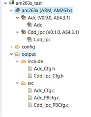
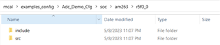
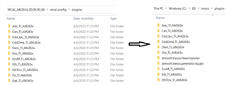
- What is the folder structure of MCAL package and how should we compile a simple MCAL application?
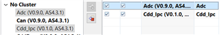
- How to use EB Tresos to generate the Configuration files?
- How to add custom EB Tresos or Vector DE configuration generated files to MCAL projects?
- How to create Multicore appimage with MCAL binary and rest of the cores to include SDK generated binaries?
- How to debug MCAL generated binaries on the Evaluation kit or Custom board using CCS Studio?
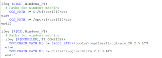
- Where to find more details about Compiler qualification and tools?

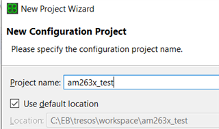
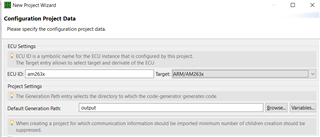
 button as shown below and Click on "Finish"to create the project.