

Part Number: MCU-PLUS-SDK-AM243X
Q1. How to tune PHY with MCU_PLUS_SDK ?
Q2. Why is PHY tuning required ?

This thread has been locked.
If you have a related question, please click the "Ask a related question" button in the top right corner. The newly created question will be automatically linked to this question.
Part Number: MCU-PLUS-SDK-AM243X
Q1. How to tune PHY with MCU_PLUS_SDK ?
Q2. Why is PHY tuning required ?
Traditionally, the OSPI controller without PHY can work at 50MHz STR mode and 25MHz DTR mode.
Due to requirements to read flash at much higher speed, the user can configure the controller at higher speed where PHY allows more flexible and power efficient transfers.
AM243x supports up-to 166MHz OSPI controller clock if PHY is enabled. But to enable the PHY, it is required to be tuned based on the Custom Board trace, Flash part used, Protocol used, STR/DTR mode enabled, Clock frequency of the controller, Dummy cycles configured etc.
Please follow the fore mentioned steps to tune the PHY in more efficient manner. We are taking MX25U51245G to follow the changes.
Also perform this experiment in dev-boot mode so the flash is not pre-configured by RBL or SBL. For more information on dev-boot mode system initialization -
Step 1
Import OSPI-FLASH-IO Project. It will show enabled Flash and OSPI.

Step 2
Configuring the MX25U to support 4S-4D-4D mode at 25MHz and test it to be functional.
Step 3
Configure the clock in OSPI mode and enable the PHY.

Note : When the PHY is enabled, the Input Clock Divider is ignored. So in this configuration even if the PHY Enablement fails, the clock is still 25MHz which is safe zone for DTR mode.
The maximum configuration supported according to datasheet is 100MHz in DTR mode for MX25U512 Flash.
Step 4
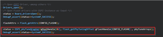
Add software in ospi_flash_io project - ospi_flash_io.c – ospi_flash_io_main
Creating a global variable of phyTuneArray as follows -

Add function to the main function.
Step 5
Run the example with Debugger connected. The intent is to get a dump of the array created i.e. phyTuneArray
This array is of 4*128*128 i.e. 64KB. Also the program execution time might take maximum 2-3 minutes.
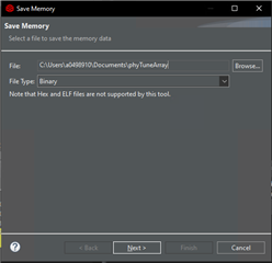
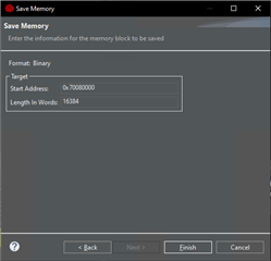
Step 6
Save the array in form of binary like this -
Step 7
Use a simple matplotlib to generate the graph for the data captured.
This is just a reference tool to generate the plot - /cfs-file/__key/communityserver-discussions-components-files/908/phy_5F00_tuning_5F00_graph_5F00_analyzer-_2800_1_2900_.py
This tool will generate something like this -

This graph can give 4 color data -
Step 8
Select the most optimum region like most center region of the graph.
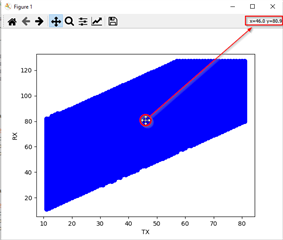
The x-axis is txDll and the y-axis is rxDll. As the graph is blue.
So in this case,
Step 9
Modify the Flash_norOspiOpen function to add the OSPI_PhyConfig params configuration, enable the PHY and disable the PHY Pipeline.
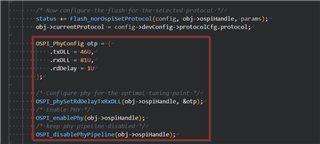
Make sure to skip the PHY Tuning Algorithm as this is not required if the data is manually added by the user.
A copy of the file is added for reference (valid for 08.06 release, may change in future) -
/*
* Copyright (C) 2021 Texas Instruments Incorporated
*
* Redistribution and use in source and binary forms, with or without
* modification, are permitted provided that the following conditions
* are met:
*
* Redistributions of source code must retain the above copyright
* notice, this list of conditions and the following disclaimer.
*
* Redistributions in binary form must reproduce the above copyright
* notice, this list of conditions and the following disclaimer in the
* documentation and/or other materials provided with the
* distribution.
*
* Neither the name of Texas Instruments Incorporated nor the names of
* its contributors may be used to endorse or promote products derived
* from this software without specific prior written permission.
*
* THIS SOFTWARE IS PROVIDED BY THE COPYRIGHT HOLDERS AND CONTRIBUTORS
* "AS IS" AND ANY EXPRESS OR IMPLIED WARRANTIES, INCLUDING, BUT NOT
* LIMITED TO, THE IMPLIED WARRANTIES OF MERCHANTABILITY AND FITNESS FOR
* A PARTICULAR PURPOSE ARE DISCLAIMED. IN NO EVENT SHALL THE COPYRIGHT
* OWNER OR CONTRIBUTORS BE LIABLE FOR ANY DIRECT, INDIRECT, INCIDENTAL,
* SPECIAL, EXEMPLARY, OR CONSEQUENTIAL DAMAGES (INCLUDING, BUT NOT
* LIMITED TO, PROCUREMENT OF SUBSTITUTE GOODS OR SERVICES; LOSS OF USE,
* DATA, OR PROFITS; OR BUSINESS INTERRUPTION) HOWEVER CAUSED AND ON ANY
* THEORY OF LIABILITY, WHETHER IN CONTRACT, STRICT LIABILITY, OR TORT
* (INCLUDING NEGLIGENCE OR OTHERWISE) ARISING IN ANY WAY OUT OF THE USE
* OF THIS SOFTWARE, EVEN IF ADVISED OF THE POSSIBILITY OF SUCH DAMAGE.
*/
#include <board/flash.h>
#include <board/flash/ospi/flash_nor_ospi.h>
#define FLASH_OSPI_JEDEC_ID_SIZE_MAX (8U)
static int32_t Flash_norOspiErase(Flash_Config *config, uint32_t blkNum);
static int32_t Flash_norOspiEraseSector(Flash_Config *config, uint32_t sectNum);
static int32_t Flash_norOspiRead(Flash_Config *config, uint32_t offset, uint8_t *buf, uint32_t len);
static int32_t Flash_norOspiWrite(Flash_Config *config, uint32_t offset, uint8_t *buf, uint32_t len);
static int32_t Flash_norOspiOpen(Flash_Config *config, Flash_Params *params);
static void Flash_norOspiClose(Flash_Config *config);
static int32_t Flash_norOspiReset(Flash_Config *config);
int32_t Flash_quirkSpansionUNHYSADisable(Flash_Config *config);
typedef struct
{
int32_t txDLL;
int32_t rxDLL;
int32_t rdDelay;
} OSPI_PhyConfig;
extern void OSPI_phySetRdDelayTxRxDLL(OSPI_Handle handle, OSPI_PhyConfig *configPoint);
uint32_t gFlashToSpiProtocolMap[] =
{
[FLASH_CFG_PROTO_1S_1S_1S] = OSPI_NOR_PROTOCOL(1,1,1,0),
[FLASH_CFG_PROTO_1S_1S_2S] = OSPI_NOR_PROTOCOL(1,1,2,0),
[FLASH_CFG_PROTO_1S_1S_4S] = OSPI_NOR_PROTOCOL(1,1,4,0),
[FLASH_CFG_PROTO_1S_1S_8S] = OSPI_NOR_PROTOCOL(1,1,8,0),
[FLASH_CFG_PROTO_4S_4S_4S] = OSPI_NOR_PROTOCOL(4,4,4,0),
[FLASH_CFG_PROTO_4S_4D_4D] = OSPI_NOR_PROTOCOL(4,4,4,1),
[FLASH_CFG_PROTO_8S_8S_8S] = OSPI_NOR_PROTOCOL(8,8,8,0),
[FLASH_CFG_PROTO_8D_8D_8D] = OSPI_NOR_PROTOCOL(8,8,8,1),
};
Flash_Fxns gFlashNorOspiFxns = {
.openFxn = Flash_norOspiOpen,
.closeFxn = Flash_norOspiClose,
.readFxn = Flash_norOspiRead,
.writeFxn = Flash_norOspiWrite,
.eraseFxn = Flash_norOspiErase,
.eraseSectorFxn = Flash_norOspiEraseSector,
.resetFxn = Flash_norOspiReset,
};
static int32_t Flash_norOspiCmdWrite(Flash_Config *config, uint8_t cmd, uint32_t cmdAddr,
uint8_t numAddrBytes, uint8_t *txBuf, uint32_t txLen)
{
int32_t status = SystemP_SUCCESS;
Flash_NorOspiObject *obj = (Flash_NorOspiObject *)(config->object);
OSPI_WriteCmdParams wrParams;
OSPI_WriteCmdParams_init(&wrParams);
wrParams.cmd = cmd;
wrParams.cmdAddr = cmdAddr;
wrParams.numAddrBytes = numAddrBytes;
wrParams.txDataBuf = txBuf;
wrParams.txDataLen = txLen;
status = OSPI_writeCmd(obj->ospiHandle, &wrParams);
return status;
}
static int32_t Flash_norOspiCmdRead(Flash_Config *config, uint8_t cmd, uint32_t cmdAddr,
uint8_t numAddrBytes, uint8_t dummyBits, uint8_t *rxBuf, uint32_t rxLen)
{
int32_t status = SystemP_SUCCESS;
Flash_NorOspiObject *obj = (Flash_NorOspiObject *)(config->object);
OSPI_ReadCmdParams rdParams;
OSPI_ReadCmdParams_init(&rdParams);
rdParams.cmd = cmd;
rdParams.cmdAddr = cmdAddr;
rdParams.numAddrBytes = numAddrBytes;
rdParams.rxDataBuf = rxBuf;
rdParams.rxDataLen = rxLen;
rdParams.dummyBits = dummyBits;
status = OSPI_readCmd(obj->ospiHandle, &rdParams);
return status;
}
static int32_t Flash_norOspiWaitReady(Flash_Config *config, uint32_t timeOut)
{
int32_t status = SystemP_SUCCESS;
Flash_DevConfig *devCfg = config->devConfig;
Flash_NorOspiObject *obj = (Flash_NorOspiObject *)(config->object);
uint8_t readStatus[2] = { 0 };
uint8_t numAddrBytes = OSPI_CMD_INVALID_OPCODE;
uint32_t cmdAddr = OSPI_CMD_INVALID_ADDR;
uint8_t cmd = devCfg->cmdRdsr;
uint8_t bitMask = devCfg->srWip;
uint8_t numBytesToRead = 1;
uint8_t dummyBits = 0;
/* Do RDSR based on xspi WIP status */
if((devCfg->xspiWipRdCmd != 0x00) && (obj->currentProtocol == FLASH_CFG_PROTO_8D_8D_8D))
{
/* Check XSPI WIP configuration */
cmd = devCfg->xspiWipRdCmd;
cmdAddr = devCfg->xspiWipReg;
numAddrBytes = obj->numAddrBytes;
bitMask = devCfg->xspiWipBit;
numBytesToRead = 2; /* Can't read odd bytes in Octal DDR mode */
dummyBits = devCfg->protocolCfg.dummyClksCmd;
}
while((status != SystemP_SUCCESS) || (timeOut > 0))
{
status = Flash_norOspiCmdRead(config, cmd, cmdAddr, numAddrBytes, dummyBits, readStatus, numBytesToRead);
if((status == SystemP_SUCCESS) && ((readStatus[0] & bitMask) == 0))
{
break;
}
timeOut--;
}
if((readStatus[0] & bitMask)==0)
{
status = SystemP_SUCCESS;
}
else
{
status = SystemP_FAILURE;
}
return status;
}
static int32_t Flash_norOspiRegRead(Flash_Config *config, uint8_t cmd, uint32_t addr, uint8_t *data)
{
int32_t status = SystemP_SUCCESS;
Flash_NorOspiObject *obj = (Flash_NorOspiObject *)(config->object);
uint8_t reg[2] = { 0 };
uint8_t numBytes = 1;
uint8_t dummyBits = OSPI_CMD_INVALID_DUMMY;
if(obj->currentProtocol == FLASH_CFG_PROTO_8D_8D_8D)
{
numBytes = 2; /* Octal DDR can't read odd number of bytes */
dummyBits = config->devConfig->protocolCfg.dummyClksCmd;
}
status = Flash_norOspiCmdRead(config, cmd, addr, obj->numAddrBytes, dummyBits, reg, numBytes);
*data = reg[0];
return status;
}
static int32_t Flash_norOspiRegWrite(Flash_Config *config, uint8_t cmd, uint32_t addr, uint8_t data)
{
int32_t status = SystemP_SUCCESS;
uint8_t regData = data;
Flash_DevConfig *devCfg = config->devConfig;
Flash_NorOspiObject *obj = (Flash_NorOspiObject *)(config->object);
status = Flash_norOspiCmdWrite(config, devCfg->cmdWren, OSPI_CMD_INVALID_ADDR, 0, NULL, 0);
/* Wait a finite interval after WREN */
if(status == SystemP_SUCCESS)
{
status = Flash_norOspiWaitReady(config, devCfg->flashBusyTimeout);
}
if(status == SystemP_SUCCESS)
{
status = Flash_norOspiCmdWrite(config, cmd, addr, obj->numAddrBytes, ®Data, 1);
}
return status;
}
static int32_t Flash_norOspiSetRegCfg(Flash_Config *config, FlashCfg_RegConfig *rCfg)
{
int32_t status = SystemP_SUCCESS;
/* Check if parameter is configured with addressed registers */
if((rCfg->cmdRegRd != 0) || (rCfg->cmdRegWr != 0))
{
uint8_t cfgReg = 0;
uint8_t statReg = 0;
if(rCfg->isAddrReg == TRUE)
{
status += Flash_norOspiRegRead(config, rCfg->cmdRegRd, rCfg->cfgReg, &cfgReg);
}
else
{
status += Flash_norOspiRegRead(config, rCfg->cmdRegRd, OSPI_CMD_INVALID_ADDR, &cfgReg);
status += Flash_norOspiRegRead(config, 0x5U, OSPI_CMD_INVALID_ADDR, &statReg);
}
if(SystemP_SUCCESS == status)
{
/* Clear the config bits in the register */
cfgReg &= ~(uint8_t)(rCfg->mask);
/* Bitwise OR the bit pattern for setting the dummyCycle selected */
cfgReg |= (rCfg->cfgRegBitP << rCfg->shift);
/* There is register config, address might not be needed */
if(rCfg->isAddrReg == TRUE)
{
status += Flash_norOspiRegWrite(config, rCfg->cmdRegWr, rCfg->cfgReg, cfgReg);
}
else
{
//status += Flash_norOspiRegWrite(config, rCfg->cmdRegWr, OSPI_CMD_INVALID_ADDR, cfgReg);
status = Flash_norOspiCmdWrite(config, 0x6U, OSPI_CMD_INVALID_ADDR, 0, NULL, 0);
uint16_t sr = cfgReg<<8U |statReg;
status += Flash_norOspiCmdWrite(config, rCfg->cmdRegWr, OSPI_CMD_INVALID_ADDR, 0, (uint8_t *)&sr, 2);
}
}
}
else
{
/* Nothing to be done */
}
return status;
}
static int32_t Flash_norOspiSet4ByteAddrMode(Flash_Config *config)
{
int32_t status = SystemP_SUCCESS;
Flash_DevConfig *devCfg = config->devConfig;
Flash_NorOspiObject *obj = (Flash_NorOspiObject *)(config->object);
if((devCfg->fourByteAddrEnSeq & (uint8_t)(1 << 0)) != 0)
{
/* Issue instruction 0xB7 without WREN */
status = Flash_norOspiCmdWrite(config, 0xB7, OSPI_CMD_INVALID_ADDR, 0, NULL, 0);
}
if((devCfg->fourByteAddrEnSeq & (uint8_t)(1 << 1)) != 0)
{
/* Issue instruction 0xB7 with WREN */
status = Flash_norOspiCmdWrite(config, devCfg->cmdWren, OSPI_CMD_INVALID_ADDR, 0, NULL, 0);
if(status == SystemP_SUCCESS)
{
status = Flash_norOspiWaitReady(config, devCfg->flashBusyTimeout);
}
status = Flash_norOspiCmdWrite(config, 0xB7, OSPI_CMD_INVALID_ADDR, 0, NULL, 0);
if(status == SystemP_SUCCESS)
{
status = Flash_norOspiWaitReady(config, devCfg->flashBusyTimeout);
}
}
if((devCfg->fourByteAddrEnSeq & (uint8_t)(1 << 2)) != 0)
{
/* Extended Register read with instr 0xC8, write with instr 0xC5 to set
* the MSByte of addr. To be taken care during read and write.
*/
obj->extAddrRegSupport = TRUE;
}
if((devCfg->fourByteAddrEnSeq & (uint8_t)(1 << 3)) != 0)
{
/* Volatile bank register used to define 4 byte mode. To be taken care
* during read and write
*/
obj->vBankAddrRegSupport = TRUE;
}
if((devCfg->fourByteAddrEnSeq & (uint8_t)(1 << 4)) != 0)
{
/* Dedicated 4 byte address instruction set, consider 4 bytes always ON */
obj->ded4bInstrSupport = TRUE;
}
return status;
}
static int32_t Flash_norOspiSetAddressBytes(Flash_Config *config, void *ospiHandle)
{
int32_t status = SystemP_SUCCESS;
Flash_DevConfig *devCfg = config->devConfig;
Flash_NorOspiObject *obj = (Flash_NorOspiObject *)(config->object);
switch (devCfg->addrByteSupport)
{
case 0:
/* Only 3 byte addressing supported, nothing to do with flash. Set OSPI driver */
OSPI_setNumAddrBytes(ospiHandle, 3);
break;
case 1:
/* Both 3 and 4 byte addressing supported. Configure flash to switch to
* 4 byte addressing if that's selected
* */
if(devCfg->enable4BAddr == TRUE)
{
Flash_norOspiSet4ByteAddrMode(config);
obj->numAddrBytes = 4;
OSPI_setNumAddrBytes(ospiHandle, 4);
}
else
{
OSPI_setNumAddrBytes(ospiHandle, 3);
}
break;
case 2:
/* Only 4 byte addressing supported. Configure flash to switch to 4 byte
* addressing
* */
Flash_norOspiSet4ByteAddrMode(config);
obj->numAddrBytes = 4;
OSPI_setNumAddrBytes(ospiHandle, 4);
break;
default:
OSPI_setNumAddrBytes(ospiHandle, 3);
break;
}
return status;
}
static int32_t Flash_setQeBit(Flash_Config *config, uint8_t qeType)
{
int32_t status = SystemP_SUCCESS;
Flash_DevConfig *devCfg = config->devConfig;
Flash_NorOspiObject *obj = (Flash_NorOspiObject *)(config->object);
uint8_t sr1 = 0, sr2 = 0, bitPos = 0;
uint32_t bFlashRegWr = 0U;
if(SystemP_SUCCESS == status)
{
switch (qeType)
{
case 0:
/* No QE bit, detects 1-1-4 based on instruction */
break;
case 1:
case 4:
case 5:
/* QE is bit 1 of SR2 */
bitPos = (uint8_t)(1 << 1);
status = Flash_norOspiCmdRead(config, devCfg->cmdRdsr, OSPI_CMD_INVALID_ADDR, obj->numAddrBytes, OSPI_CMD_INVALID_DUMMY, &sr1, 1);
status += Flash_norOspiCmdRead(config, 0x35, OSPI_CMD_INVALID_ADDR, obj->numAddrBytes, OSPI_CMD_INVALID_DUMMY, &sr2, 1);
if((sr2 & bitPos) != 0)
{
/* QE bit already set */
}
else
{
uint16_t sr = 0;
sr2 |= bitPos;
sr = ((sr2 << 8) | sr1);
status = Flash_norOspiCmdWrite(config, devCfg->cmdWren, OSPI_CMD_INVALID_ADDR, 0, NULL, 0);
if(status == SystemP_SUCCESS)
{
status = Flash_norOspiWaitReady(config, devCfg->flashBusyTimeout);
}
status += Flash_norOspiCmdWrite(config, 0x01, OSPI_CMD_INVALID_ADDR, obj->numAddrBytes, (uint8_t *)&sr, 2);
bFlashRegWr = 1U;
}
break;
case 2:
/* QE is bit 6 of SR1 */
sr1 = 0;
bitPos = (uint8_t)(1 << 6);
status = Flash_norOspiCmdRead(config, devCfg->cmdRdsr, OSPI_CMD_INVALID_ADDR, obj->numAddrBytes, OSPI_CMD_INVALID_DUMMY, &sr1, 1);
if((sr1 & bitPos) != 0)
{
/* QE is already set */
}
else
{
sr1 |= bitPos;
status = Flash_norOspiCmdWrite(config, devCfg->cmdWren, OSPI_CMD_INVALID_ADDR, 0, NULL, 0);
if(status == SystemP_SUCCESS)
{
status = Flash_norOspiWaitReady(config, devCfg->flashBusyTimeout);
}
status += Flash_norOspiCmdWrite(config, 0x01, OSPI_CMD_INVALID_ADDR, obj->numAddrBytes, &sr1, 1);
bFlashRegWr = 1U;
}
break;
case 3:
/* QE is bit 7 of SR2 */
sr2 = 0;
bitPos = (uint8_t)(1 << 7);
status = Flash_norOspiCmdRead(config, 0x3F, OSPI_CMD_INVALID_ADDR, obj->numAddrBytes, OSPI_CMD_INVALID_DUMMY, &sr2, 1);
if((sr2 & bitPos) != 0)
{
/* QE is already set */
}
else
{
sr2 |= bitPos;
status = Flash_norOspiCmdWrite(config, devCfg->cmdWren, OSPI_CMD_INVALID_ADDR, 0, NULL, 0);
if(status == SystemP_SUCCESS)
{
status = Flash_norOspiWaitReady(config, devCfg->flashBusyTimeout);
}
status += Flash_norOspiCmdWrite(config, 0x3E, OSPI_CMD_INVALID_ADDR, obj->numAddrBytes, &sr2, 1);
bFlashRegWr = 1U;
}
break;
case 6:
/* QE is bit 1 of SR2, using different command */
bitPos = (uint8_t)(1 << 1);
status = Flash_norOspiCmdRead(config, 0x35, OSPI_CMD_INVALID_ADDR, obj->numAddrBytes, OSPI_CMD_INVALID_DUMMY, &sr2, 1);
if((sr2 & bitPos) != 0)
{
/* QE bit already set */
}
else
{
sr2 |= bitPos;
status = Flash_norOspiCmdWrite(config, devCfg->cmdWren, OSPI_CMD_INVALID_ADDR, 0, NULL, 0);
if(status == SystemP_SUCCESS)
{
status = Flash_norOspiWaitReady(config, devCfg->flashBusyTimeout);
}
status += Flash_norOspiCmdWrite(config, 0x31, OSPI_CMD_INVALID_ADDR, obj->numAddrBytes, &sr2, 1);
bFlashRegWr = 1U;
}
break;
default:
break;
}
if((status == SystemP_SUCCESS) && (1U == bFlashRegWr))
{
status = Flash_norOspiWaitReady(config, devCfg->flashBusyTimeout);
}
}
return status;
}
static int32_t Flash_setOeBit(Flash_Config *config, uint8_t oeType)
{
int32_t status = SystemP_SUCCESS;
Flash_DevConfig *devCfg = config->devConfig;
Flash_NorOspiObject *obj = (Flash_NorOspiObject *)(config->object);
uint8_t sr2 = 0, bitPos = 0;
/* oeType 0 means no config, and all other values other 1 are reserved for now */
switch (oeType)
{
case 0:
/* No octal enable bit */
break;
case 1:
/* Octal enable is the bit 3 of SR2 */
bitPos = (uint8_t)(1 << 3);
status = Flash_norOspiCmdRead(config, 0x65, OSPI_CMD_INVALID_ADDR, 2, 1, &sr2, 1);
if((sr2 & bitPos) != 0)
{
/* QE is already set */
}
else
{
sr2 |= bitPos;
status = Flash_norOspiCmdWrite(config, devCfg->cmdWren, OSPI_CMD_INVALID_ADDR, 0, NULL, 0);
if(status == SystemP_SUCCESS)
{
status = Flash_norOspiWaitReady(config, devCfg->flashBusyTimeout);
}
status += Flash_norOspiCmdWrite(config, 0x3E, OSPI_CMD_INVALID_ADDR, obj->numAddrBytes, &sr2, 1);
}
break;
default:
break;
}
return status;
}
static int32_t Flash_norOspiSetModeDummy(Flash_Config *config, void *ospiHandle)
{
int32_t status = SystemP_SUCCESS;
Flash_DevConfig *devCfg = config->devConfig;
FlashCfg_ProtoEnConfig *pCfg = &(devCfg->protocolCfg);
if(pCfg->modeClksCmd != 0)
{
OSPI_enableModeBitsCmd(ospiHandle);
}
if(pCfg->modeClksRd != 0)
{
OSPI_setModeBits(ospiHandle, pCfg->modeClksRd);
OSPI_enableModeBitsRead(ospiHandle);
}
OSPI_setReadDummyCycles(ospiHandle, pCfg->dummyClksRd);
OSPI_setCmdDummyCycles(ospiHandle, pCfg->dummyClksCmd);
if((pCfg->dummyClksCmd != 0) || (pCfg->dummyClksRd != 0))
{
FlashCfg_RegConfig *dCfg = &(pCfg->dummyCfg);
status = Flash_norOspiSetRegCfg(config, dCfg);
if(status == SystemP_SUCCESS)
{
status = Flash_norOspiWaitReady(config, devCfg->flashBusyTimeout);
}
}
return status;
}
static int32_t Flash_norOspiSetDTR(Flash_Config *config, void *ospiHandle)
{
int32_t status = SystemP_SUCCESS;
if((config == NULL) || (NULL == ospiHandle))
{
status = SystemP_FAILURE;
}
else
{
Flash_DevConfig *devCfg = config->devConfig;
Flash_NorOspiObject *obj = (Flash_NorOspiObject *)(config->object);
FlashCfg_RegConfig *dtrCfg = &(devCfg->protocolCfg.strDtrCfg);
/* Check if STR/DTR is configured with addressed registers */
status = Flash_norOspiSetRegCfg(config, dtrCfg);
if(devCfg->protocolCfg.protocol == FLASH_CFG_PROTO_8D_8D_8D)
{
obj->currentProtocol = FLASH_CFG_PROTO_8D_8D_8D;
}
status = Flash_norOspiWaitReady(config, devCfg->flashBusyTimeout);
}
return status;
}
static int32_t Flash_set444mode(Flash_Config *config, uint8_t seq)
{
int32_t status = SystemP_SUCCESS;
Flash_DevConfig *devCfg = config->devConfig;
FlashCfg_ProtoEnConfig *pCfg = &(devCfg->protocolCfg);
Flash_NorOspiObject *obj = (Flash_NorOspiObject *)(config->object);
uint32_t seqFound = 0U;
if((seq & (uint8_t)(1 << 0)) != 0)
{
/* Issue instruction 0x38 */
status = Flash_norOspiCmdWrite(config, 0x38, OSPI_CMD_INVALID_ADDR, 0, NULL, 0);
seqFound = 1U;
}
if((seq & (uint8_t)(1 << 1)) != 0)
{
/* Issue instruction 0x38 */
status = Flash_norOspiCmdWrite(config, 0x38, OSPI_CMD_INVALID_ADDR, 0, NULL, 0);
seqFound = 1U;
}
if((seq & (uint8_t)(1 << 2)) != 0)
{
/* Issue instruction 0x35 */
status = Flash_norOspiCmdWrite(config, 0x35, OSPI_CMD_INVALID_ADDR, 0, NULL, 0);
seqFound = 1U;
}
if((seq & (uint8_t)(1 << 3)) != 0)
{
/* Read modify write of reg, set bit 6 */
uint8_t reg = 0;
Flash_norOspiRegRead(config, 0x65, 0x800003, ®);
if((reg & (1 << 6)) != 0)
{
/* 444 mode already set */
}
else
{
reg |= (1 << 6);
Flash_norOspiRegWrite(config, 0x71, 0x800003, reg);
}
seqFound = 1U;
}
if((seq & (uint8_t)(1 << 4)) != 0)
{
/* Read modify write of reg, clear bit 7 */
uint8_t reg = 0;
Flash_norOspiRegRead(config, 0x65, OSPI_CMD_INVALID_ADDR, ®);
if((reg >> 7) == 0)
{
/* 444 mode already set */
}
else
{
reg &= ~(1 << 7);
Flash_norOspiRegWrite(config, 0x61, OSPI_CMD_INVALID_ADDR, reg);
}
seqFound = 1U;
}
if(seqFound)
{
OSPI_setProtocol((OSPI_Handle)(obj->ospiHandle), gFlashToSpiProtocolMap[pCfg->protocol]);
obj->currentProtocol = pCfg->protocol;
}
status = Flash_norOspiWaitReady(config, devCfg->flashBusyTimeout);
return status;
}
static int32_t Flash_set888mode(Flash_Config *config, uint8_t seq)
{
int32_t status = SystemP_SUCCESS;
Flash_NorOspiObject *obj = (Flash_NorOspiObject *)(config->object);
Flash_DevConfig *devCfg = config->devConfig;
FlashCfg_ProtoEnConfig *pCfg = &(devCfg->protocolCfg);
if((seq & (1 << 1)) != 0)
{
status = Flash_norOspiCmdWrite(config, 0xE8, OSPI_CMD_INVALID_ADDR, 0, NULL, 0);
OSPI_setProtocol((OSPI_Handle)(obj->ospiHandle), gFlashToSpiProtocolMap[pCfg->protocol]);
obj->currentProtocol = pCfg->protocol;
if(status == SystemP_SUCCESS)
{
status = Flash_norOspiWaitReady(config, devCfg->flashBusyTimeout);
}
}
if((seq & (1 << 2)) != 0)
{
status = Flash_norOspiCmdWrite(config, devCfg->cmdWren, OSPI_CMD_INVALID_ADDR, 0, NULL, 0);
if(status == SystemP_SUCCESS)
{
status = Flash_norOspiWaitReady(config, devCfg->flashBusyTimeout);
}
status = Flash_norOspiCmdWrite(config, 0x72, 0, 0, NULL, 0);
OSPI_setProtocol((OSPI_Handle)(obj->ospiHandle), gFlashToSpiProtocolMap[pCfg->protocol]);
obj->currentProtocol = pCfg->protocol;
if(status == SystemP_SUCCESS)
{
status = Flash_norOspiWaitReady(config, devCfg->flashBusyTimeout);
}
}
/* Check for register addressed 8-8-8 mode */
FlashCfg_RegConfig *octCfg = &(devCfg->protocolCfg.protoCfg);
FlashCfg_RegConfig *dCfg = &(devCfg->protocolCfg.strDtrCfg);
if(octCfg->isAddrReg && dCfg->isAddrReg && (dCfg->cfgReg == octCfg->cfgReg))
{
/* Do both the configs together */
uint8_t reg = 0U;
status = Flash_norOspiRegRead(config, octCfg->cmdRegRd, octCfg->cfgReg, ®);
if(SystemP_SUCCESS == status)
{
/* Octal DDR is special. Check if it is already enabled */
if((((reg >> octCfg->shift) & 0x01) == 1) && (((reg >> dCfg->shift) & 0x01) == 1))
{
/* Already 8D */
}
else
{
/* Clear the config bits in the register */
reg &= ~(uint8_t)(octCfg->mask | dCfg->mask);
/* Bitwise OR the bit pattern for setting the dummyCycle selected */
reg |= (octCfg->cfgRegBitP << octCfg->shift);
if(pCfg->protocol == FLASH_CFG_PROTO_8D_8D_8D)
{
reg |= (dCfg->cfgRegBitP << dCfg->shift);
}
status += Flash_norOspiRegWrite(config, octCfg->cmdRegWr, octCfg->cfgReg, reg);
}
}
OSPI_setProtocol((OSPI_Handle)(obj->ospiHandle), gFlashToSpiProtocolMap[pCfg->protocol]);
}
else
{
Flash_norOspiSetRegCfg(config, octCfg);
Flash_norOspiWaitReady(config, devCfg->flashBusyTimeout);
Flash_norOspiSetRegCfg(config, dCfg);
if(pCfg->protocol == FLASH_CFG_PROTO_8D_8D_8D)
{
obj->currentProtocol = pCfg->protocol;
}
Flash_norOspiWaitReady(config, devCfg->flashBusyTimeout);
}
if(status == SystemP_SUCCESS)
{
obj->currentProtocol = pCfg->protocol;
}
return status;
}
static int32_t Flash_norOspiSetProtocol(Flash_Config *config, void *ospiHandle, Flash_Params *params)
{
int32_t status = SystemP_SUCCESS;
if((config == NULL) || (NULL == ospiHandle))
{
status = SystemP_FAILURE;
}
else
{
Flash_DevConfig *devCfg = config->devConfig;
/* Configure the flash according to protocol */
uint32_t protocol = devCfg->protocolCfg.protocol;
FlashCfg_ProtoEnConfig *pCfg = &(devCfg->protocolCfg);
if(FLASH_CFG_PROTO_CUSTOM == protocol)
{
status += params->custProtoFxn(config);
}
else
{
/* OOB support available for:
* 1S_1S_1S
* 1S_1S_2S
* 1S_1S_4S
* 1S_1S_8S
* 4S_4S_4S
* 4S_4D_4D
* 8S_8S_8S
* 8D_8D_8D
*/
switch (protocol)
{
case FLASH_CFG_PROTO_1S_1S_1S:
/* No config needed for flash driver, set commands */
OSPI_setXferOpCodes(ospiHandle, pCfg->cmdRd, pCfg->cmdWr);
break;
case FLASH_CFG_PROTO_1S_1S_2S:
/* No config needed for flash driver. Set commands, mode and dummy cycle if needed */
/* Check for mode Bits for 1-1-2 mode */
break;
case FLASH_CFG_PROTO_1S_1S_4S:
/* Set Quad Enable Bit. Set commands, mode and dummy cycle if needed */
/* Set QE bit */
status += Flash_setQeBit(config, pCfg->enableType);
break;
case FLASH_CFG_PROTO_1S_1S_8S:
/* Set Octal Enable Bit. Set commands, mode and dummy cycle if needed */
/* Set OE bit */
status += Flash_setOeBit(config, pCfg->enableType);
break;
case FLASH_CFG_PROTO_4S_4S_4S:
case FLASH_CFG_PROTO_4S_4D_4D:
/* Set Quad Enable Bit. Set 444 mode. Set commands, mode and dummy cycle if needed.
* In case of DTR, enable that too*/
/* Set QE bit */
status += Flash_setQeBit(config, pCfg->enableType);
/* Set 444 mode */
status += Flash_set444mode(config, pCfg->enableSeq);
break;
case FLASH_CFG_PROTO_8S_8S_8S:
case FLASH_CFG_PROTO_8D_8D_8D:
/* Set Octal Enable Bit. Set 444 mode. Set commands, mode and dummy cycle if needed */
/* Set OE bit */
status = Flash_setOeBit(config, pCfg->enableType);
/* Set 888 mode */
status += Flash_set888mode(config, pCfg->enableSeq);
break;
default:
status = SystemP_FAILURE;
break;
}
if(SystemP_SUCCESS == status)
{
OSPI_setProtocol((OSPI_Handle)ospiHandle, gFlashToSpiProtocolMap[protocol]);
}
}
}
return status;
}
static int32_t Flash_norOspiReadId(Flash_Config *config)
{
int32_t status = SystemP_SUCCESS;
Flash_NorOspiObject *obj = (Flash_NorOspiObject *)(config->object);
Flash_DevConfig *devCfg = config->devConfig;
FlashCfg_ReadIDConfig *idCfg = &(devCfg->idCfg);
uint8_t idCode[FLASH_OSPI_JEDEC_ID_SIZE_MAX];
uint32_t cmdAddr = OSPI_CMD_INVALID_ADDR;
uint32_t dummyBits = 0;
uint32_t idNumBytes = 3;
uint32_t numAddrBytes = 0;
if(obj->currentProtocol == FLASH_CFG_PROTO_8D_8D_8D)
{
dummyBits = 4;
cmdAddr = 0U;
numAddrBytes = obj->numAddrBytes;
idNumBytes = 4; /* Can't read odd bytes in octal DDR */
}
else
{
/* default config */
}
status = Flash_norOspiCmdRead(config, idCfg->cmd, cmdAddr, numAddrBytes, dummyBits, idCode, idNumBytes);
/* Verify ID with filled data */
if (status == SystemP_SUCCESS)
{
uint32_t manfID, devID;
manfID = (uint32_t)idCode[0];
devID = ((uint32_t)idCode[1] << 8) | ((uint32_t)idCode[2]);
if (!((manfID == config->attrs->manufacturerId) && (devID == config->attrs->deviceId)))
{
/* Try the other 3 bytes */
manfID = (uint32_t)idCode[3];
devID = ((uint32_t)idCode[4] << 8) | ((uint32_t)idCode[5]);
if (!((manfID == config->attrs->manufacturerId) && (devID == config->attrs->deviceId)))
{
status = SystemP_FAILURE;
}
}
else
{
/* Success, nothing to do */;
}
}
return status;
}
static int32_t Flash_norOspiRead(Flash_Config *config, uint32_t offset, uint8_t *buf, uint32_t len)
{
int32_t status = SystemP_SUCCESS;
Flash_NorOspiObject *obj = (Flash_NorOspiObject *)(config->object);
Flash_Attrs *attrs = config->attrs;
if(obj->phyEnable)
{
OSPI_enablePhy(obj->ospiHandle);
}
/* Validate address input */
if ((offset + len) > (attrs->flashSize))
{
status = SystemP_FAILURE;
}
if (status == SystemP_SUCCESS)
{
OSPI_Transaction transaction;
OSPI_Transaction_init(&transaction);
transaction.addrOffset = offset;
transaction.buf = (void *)buf;
transaction.count = len;
status = OSPI_readDirect(obj->ospiHandle, &transaction);
}
if(obj->phyEnable)
{
OSPI_disablePhy(obj->ospiHandle);
}
return status;
}
static int32_t Flash_norOspiWrite(Flash_Config *config, uint32_t offset, uint8_t *buf, uint32_t len)
{
int32_t status = SystemP_SUCCESS;
Flash_NorOspiObject *obj = (Flash_NorOspiObject *)(config->object);
Flash_DevConfig *devCfg = config->devConfig;
Flash_Attrs *attrs = config->attrs;
/* Validate address input */
if((offset + len) > (attrs->flashSize))
{
status = SystemP_FAILURE;
}
/* Check if the offset is aligned to page */
if(0 != (offset % attrs->pageSize))
{
status = SystemP_FAILURE;
}
if(SystemP_SUCCESS == status)
{
uint32_t pageSize, chunkLen, actual;
OSPI_Transaction transaction;
pageSize = attrs->pageSize;
chunkLen = pageSize;
for (actual = 0; actual < len; actual += chunkLen)
{
status = Flash_norOspiCmdWrite(config, devCfg->cmdWren, OSPI_CMD_INVALID_ADDR, 0, NULL, 0);
if(status == SystemP_SUCCESS)
{
status = Flash_norOspiWaitReady(config, devCfg->flashBusyTimeout);
}
if(status == SystemP_SUCCESS)
{
/* Send Page Program command */
if((len - actual) < (pageSize))
{
chunkLen = (len - actual);
}
else
{
chunkLen = pageSize;
}
OSPI_Transaction_init(&transaction);
transaction.addrOffset = offset;
transaction.buf = (void *)(buf + actual);
transaction.count = chunkLen;
status = OSPI_writeIndirect(obj->ospiHandle, &transaction);
}
if(status == SystemP_SUCCESS)
{
status = Flash_norOspiWaitReady(config, devCfg->flashWriteTimeout);
}
if(status == SystemP_SUCCESS)
{
offset += chunkLen;
}
else
{
break;
}
}
}
return status;
}
static int32_t Flash_norOspiErase(Flash_Config *config, uint32_t blkNum)
{
int32_t status = SystemP_SUCCESS;
Flash_NorOspiObject *obj = (Flash_NorOspiObject *)(config->object);
Flash_Attrs *attrs = config->attrs;
Flash_DevConfig *devCfg = config->devConfig;
uint8_t cmd = OSPI_CMD_INVALID_OPCODE;
uint32_t cmdAddr = OSPI_CMD_INVALID_ADDR;
if(blkNum == (uint32_t)(-1))
{
cmd = devCfg->eraseCfg.cmdChipErase;
}
else
{
cmdAddr = blkNum * attrs->blockSize;
if(obj->numAddrBytes == 3)
{
cmd = devCfg->eraseCfg.cmdBlockErase3B;
}
else
{
cmd = devCfg->eraseCfg.cmdBlockErase4B;
}
if(blkNum >= attrs->blockCount)
{
status = SystemP_FAILURE;
}
}
if(SystemP_SUCCESS == status)
{
status = Flash_norOspiWaitReady(config, devCfg->flashBusyTimeout);
}
if(SystemP_SUCCESS == status)
{
status = Flash_norOspiCmdWrite(config, devCfg->cmdWren, OSPI_CMD_INVALID_ADDR, 0, NULL, 0);
}
if(SystemP_SUCCESS == status)
{
status = Flash_norOspiWaitReady(config, devCfg->flashBusyTimeout);
}
if(SystemP_SUCCESS == status)
{
status = Flash_norOspiCmdWrite(config, cmd, cmdAddr, obj->numAddrBytes, NULL, 0);
}
if(SystemP_SUCCESS == status)
{
status = Flash_norOspiWaitReady(config, devCfg->flashBusyTimeout);
}
return status;
}
static int32_t Flash_norOspiEraseSector(Flash_Config *config, uint32_t sectorNum)
{
int32_t status = SystemP_SUCCESS;
Flash_NorOspiObject *obj = (Flash_NorOspiObject *)(config->object);
Flash_Attrs *attrs = config->attrs;
Flash_DevConfig *devCfg = config->devConfig;
uint8_t cmd = OSPI_CMD_INVALID_OPCODE;
uint32_t cmdAddr = OSPI_CMD_INVALID_ADDR;
if(sectorNum == (uint32_t)(-1))
{
cmd = devCfg->eraseCfg.cmdChipErase;
}
else
{
cmdAddr = sectorNum * attrs->sectorSize;
if(obj->numAddrBytes == 3)
{
cmd = devCfg->eraseCfg.cmdSectorErase3B;
}
else
{
cmd = devCfg->eraseCfg.cmdSectorErase4B;
}
if(sectorNum >= attrs->sectorCount)
{
status = SystemP_FAILURE;
}
}
if(SystemP_SUCCESS == status)
{
status = Flash_norOspiWaitReady(config, devCfg->flashBusyTimeout);
}
if(SystemP_SUCCESS == status)
{
status = Flash_norOspiCmdWrite(config, devCfg->cmdWren, OSPI_CMD_INVALID_ADDR, 0, NULL, 0);
}
if(SystemP_SUCCESS == status)
{
status = Flash_norOspiWaitReady(config, devCfg->flashBusyTimeout);
}
if(SystemP_SUCCESS == status)
{
status = Flash_norOspiCmdWrite(config, cmd, cmdAddr, obj->numAddrBytes, NULL, 0);
}
if(SystemP_SUCCESS == status)
{
status = Flash_norOspiWaitReady(config, devCfg->flashBusyTimeout);
}
return status;
}
static int32_t Flash_norOspiReset(Flash_Config *config)
{
int32_t status = SystemP_SUCCESS;
Flash_NorOspiObject *obj = (Flash_NorOspiObject *)(config->object);
Flash_DevConfig *devCfg = config->devConfig;
if((devCfg->resetType & (uint8_t)(0x07)) != 0)
{
uint32_t clocks = 0;
if((devCfg->resetType & (uint8_t)(0x01)) != 0)
{
clocks = 8;
}
if((devCfg->resetType & (uint8_t)(0x02)) != 0)
{
clocks = 10;
}
if((devCfg->resetType & (uint8_t)(0x04)) != 0)
{
clocks = 16;
}
if(clocks == 0)
{
status = SystemP_FAILURE;
}
else
{
if((clocks == 10) && (obj->numAddrBytes != 4))
{
clocks = 8;
}
while(clocks--)
{
Flash_norOspiCmdWrite(config, 0x0F, OSPI_CMD_INVALID_ADDR, 0, NULL, 0);
}
}
}
if((devCfg->resetType & (uint8_t)(0x08)) != 0)
{
/* Issue instruction 0xF0 */
status = Flash_norOspiCmdWrite(config, 0xF0, OSPI_CMD_INVALID_ADDR, 0, NULL, 0);
}
if((devCfg->resetType & (uint8_t)(0x10)) != 0)
{
/* Issue reset enable, and then reset command */
status = Flash_norOspiCmdWrite(config, 0x66, OSPI_CMD_INVALID_ADDR, 0, NULL, 0);
if(SystemP_SUCCESS == status)
{
status = Flash_norOspiCmdWrite(config, 0x99, OSPI_CMD_INVALID_ADDR, 0, NULL, 0);
}
}
Flash_norOspiWaitReady(config, devCfg->flashBusyTimeout);
return status;
}
static int32_t Flash_norOspiOpen(Flash_Config *config, Flash_Params *params)
{
int32_t status = SystemP_SUCCESS;
Flash_NorOspiObject *obj = (Flash_NorOspiObject *)(config->object);
Flash_Attrs *attrs = config->attrs;
int32_t attackVectorStatus = SystemP_FAILURE;
obj->ospiHandle = OSPI_getHandle(attrs->driverInstance);
if(obj->ospiHandle == NULL)
{
status = SystemP_FAILURE;
}
if(SystemP_SUCCESS == status)
{
/* Set device size and addressing bytes */
OSPI_setDeviceSize(obj->ospiHandle, attrs->pageSize, attrs->blockSize);
/* Set command opcode extension type */
OSPI_setCmdExtType(obj->ospiHandle, config->devConfig->cmdExtType);
/* Set initial number of address bytes */
obj->numAddrBytes = 3;
/* Set current protocol as 1s1s1s */
obj->currentProtocol = FLASH_CFG_PROTO_1S_1S_1S;
/* Set number of address bytes. If 4 byte addressing is supported, switch to that */
status += Flash_norOspiSetAddressBytes(config, obj->ospiHandle);
/* Set opcodes in OSPI controller */
OSPI_setXferOpCodes(obj->ospiHandle, config->devConfig->protocolCfg.cmdRd, config->devConfig->protocolCfg.cmdWr);
/* Set Mode Clocks and Dummy Clocks in Controller and Flash Memory */
status += Flash_norOspiSetModeDummy(config, obj->ospiHandle);
/* Set RD Capture Delay by reading ID */
uint32_t readDataCapDelay = 4U;
OSPI_setRdDataCaptureDelay(obj->ospiHandle, readDataCapDelay);
status = Flash_norOspiReadId(config);
while((status != SystemP_SUCCESS) && (readDataCapDelay > 0U))
{
readDataCapDelay--;
OSPI_setRdDataCaptureDelay(obj->ospiHandle, readDataCapDelay);
status = Flash_norOspiReadId(config);
}
/* Now configure the flash for the selected protocol */
status += Flash_norOspiSetProtocol(config, obj->ospiHandle, params);
obj->currentProtocol = config->devConfig->protocolCfg.protocol;
OSPI_PhyConfig otp = {
.txDLL = 46U,
.rxDLL = 81U,
.rdDelay = 1U
};
/* Configure phy for the optimal tuning point */
OSPI_phySetRdDelayTxRxDLL(obj->ospiHandle, &otp);
/* Enable PHY */
OSPI_enablePhy(obj->ospiHandle);
/* keep phy pipeline disabled */
OSPI_disablePhyPipeline(obj->ospiHandle);
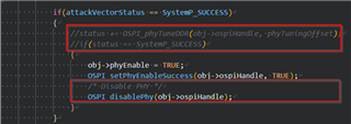
/* Enable PHY if attack vector present and PHY mode is enabled */
uint32_t phyTuningOffset = Flash_getPhyTuningOffset(config);
if(OSPI_isPhyEnable(obj->ospiHandle))
{
attackVectorStatus = OSPI_phyReadAttackVector(obj->ospiHandle, phyTuningOffset);
if(attackVectorStatus != SystemP_SUCCESS)
{
/* Flash the attack vector to the last block */
uint32_t sect = 0, page = 0;
uint32_t phyTuningData = 0,phyTuningDataSize = 0;
OSPI_phyGetTuningData(&phyTuningData, &phyTuningDataSize);
Flash_offsetToSectorPage(config, phyTuningOffset, §, &page);
Flash_norOspiEraseSector(config, sect);
Flash_norOspiWrite(config, phyTuningOffset, (uint8_t *)phyTuningData, phyTuningDataSize);
attackVectorStatus = OSPI_phyReadAttackVector(obj->ospiHandle, phyTuningOffset);
}
if(attackVectorStatus == SystemP_SUCCESS)
{
//status += OSPI_phyTuneDDR(obj->ospiHandle, phyTuningOffset);
//if(status == SystemP_SUCCESS)
{
obj->phyEnable = TRUE;
OSPI_setPhyEnableSuccess(obj->ospiHandle, TRUE);
/* Disable PHY */
OSPI_disablePhy(obj->ospiHandle);
}
}
else
{
DebugP_logError("%s : PHY enabling failed!!! Continuing without PHY...\r\n", __func__);
obj->phyEnable = FALSE;
OSPI_setPhyEnableSuccess(obj->ospiHandle, FALSE);
}
}
else
{
obj->phyEnable = FALSE;
}
}
/* Any flash specific quirks, like hybrid sector config etc. */
if(params->quirksFxn != NULL)
{
params->quirksFxn(config);
}
else
{
/* Do nothing */
}
return status;
}
static void Flash_norOspiClose(Flash_Config *config)
{
Flash_NorOspiObject *obj = (Flash_NorOspiObject *)(config->object);
obj->ospiHandle = NULL;
/* OSPI Driver will be closed outside flash */
return;
}
int32_t Flash_quirkSpansionUNHYSADisable(Flash_Config *config)
{
int32_t status = SystemP_SUCCESS;
uint8_t regData = 0x00;
uint32_t write = 0;
/* Hybrid Sector Disable */
status = Flash_norOspiRegRead(config, 0x65, 0x00800004, ®Data);
if(status == SystemP_SUCCESS)
{
if((regData & ((uint8_t)(1 << 3))) == 0)
{
/* Set UNHYSA bit */
regData |= (1 << 3);
write = 1U;
}
else
{
/* No action */
}
}
if(write)
{
status = Flash_norOspiRegWrite(config, 0x71, 0x04, regData);
}
return status;
}
Step 10
Try the ospi_flash_io example by removing the OSPI_PhyGrapher from the program flow. Now your PHY is enabled which allows OSPI controller at 100MHz.
Special Notes :
