Other Parts Discussed in Thread: AM2631, SYSCONFIG
Hi
I have designed my own board based on AM2634 MCU and try to connect and load the program via XDS110.
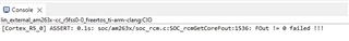
I get the following error: "ASSERT: 0.1s: soc/am263x/soc_rcm.c:SOC_rcmGetCoreFout:1536: FOut != 0 failed !!!" when I try to load the program.
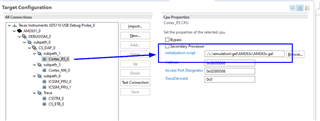
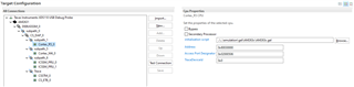
Is there any change that I should made in AM2631.ccxml?
and how about the boot modes? must it be in "No boot" mode?
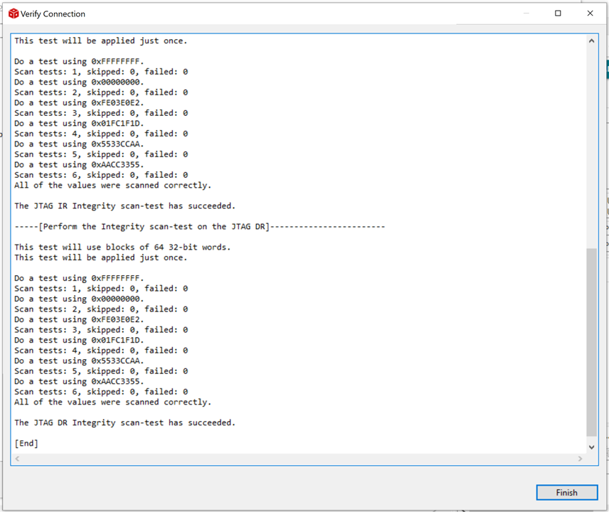
By the way, the connection seems to be OK.
Thanks
Saman