This thread has been locked.

If you have a related question, please click the "Ask a related question" button in the top right corner. The newly created question will be automatically linked to this question.

AM2434: Clock High and Low Time OSPI

Part Number: AM2434

Hi Experts,

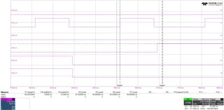
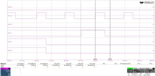
we have a QUAD SPI NOR Flash connected to the OSPI of the am243x and run it in QPI mode 4s-4s-4s. We noticed when recording with the oscillator that the high and low times of the clock do not match. In the manual of the flash 50% +-5% are allowed. I have made screenshots and attached them. One with 50MHz and one with 100MHz Clock. Can the high and low times be adjusted via register?
  • Hello,

    There are no MMRs to modify the high and low time. From inspecting your waveforms we can see that the high times are not meeting the required spec in the datasheet for correct operation, the high time is falling short

    Can you please share what your QSPI schematic block looks like? Also, what flash device are you working with? have you tried using any of the code from our SDK to cross check against existing software? 

    Best,

    Daniel 

  • Hi,

    we have not made any changes to the OSPI drivers. We had to adjust the Flash drivers in a few places.

    We use this flash S25FS512SAGMFI013 in QPI Mode 4s-4s-4s normally with 50MHz.

    Regards,

    Matthias

  • Hi Matthias,

    What updates did you make in the Flash Drivers and with what purpose? I'm trying to understand if these can be the result of software changes

    Best,

    Daniel

  • Hi Daniel,

    we have changed the sequence of the initialisation steps in the Flash Driver.

    Is it possible that some CLK divider is in an unfavourable position? Measurements show that the lower the clock, the better the timings.

    Did you notice anything wrong with the schematic plan or does it fit so far?

    Regards,

    Matthias

  • Hi Matthias, 

    I do not see any discrepancy in the schematic, but it is already very unlikely this problem stems from circuit design. I will reach out to the other experts for comment on this so please allow until Monday for more information 

    Best,

    Daniel

  • Hi Matthias, 

    I apologize for the wait, the experts have yet to give comment on this. I will push the question to try to get an answer by early next week 

    Best,

    Daniel 

  • Hi Matthias,

    Can you please elaborate on the following: 

    • What reference clock are you using to generate the OSPI_CLK?
    • What initialization steps did you modify in the flash drivers? 

    Best,

    Daniel 

  • Hi Daniel,

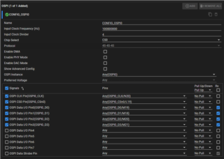
    this is our OSPI configuration. The steps we have changed have to do exclusively with writing the flash registers. The reference clock ist 25MHz.

    Regards,

    Matthias

  • Hi Daniel,

    so far we have measured with the digital probe of the oscilloscope and it seems that this is where the deviations come from. We have now measured with the analog probe and the timings there look very good. So far we cannot explain where the measurement errors in the digital part come from. The problem was probably on our side.
    I still have a question about the diagrams in the datasheet under 7.10.5.14.2. In Figure 7-85, the rising edge is data launch and the falling edge is data capture. In Figure 7.86, the falling edge is data launch and the rising edge is data capture. These are different modes. Are the diagrams wrong?
    If I use the formula in Figure 7-85 O19, I get negative setup timings. (10,4 - (0,975*4*5)). Is the formula wrong or am I using the wrong values? CaptureDelay=4 and refclk in ns=5.

    Regards,

    Matthias

  • Hi Matthias,

    Different launch and capture edges do represent different modes but that should not affect the formulas, the diagrams are different modes but still applicable. Also, a negative setup time is fine as long as you have a positive hold time after the setup time.

    Setup time is the time the data has to be stable before a clock edge. A negative time means that the data can be stable after the edge. However, this means that the hold time will have to be adjusted and it will result in a greater positive number. As it would be in your case given the calculations:

    Tsu = (10.4 - (0.975 * 4 * 5)) = -9.1

    Th  = (0.7 + (0.975 * 4 * 5)) = 20.2

    Your calculations are correct.

    Best,

    Daniel