- Ask a related questionWhat is a related question?A related question is a question created from another question. When the related question is created, it will be automatically linked to the original question.

Hi Team,
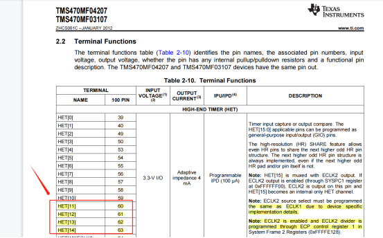
tms470mf03107 HET module pin description:
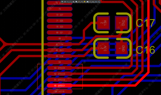
PCB 4 PWM pin layout:
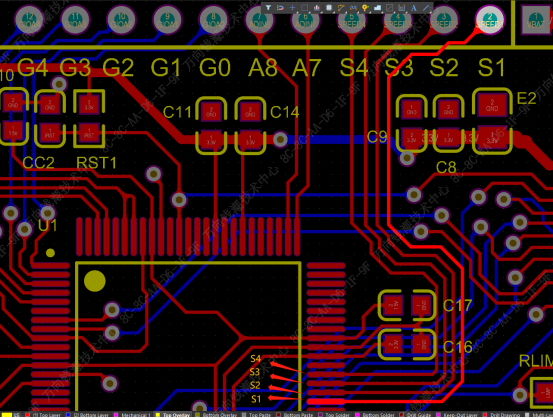
After ZOOM in:
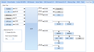
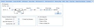
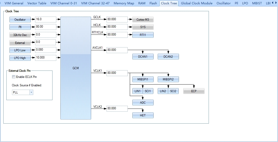
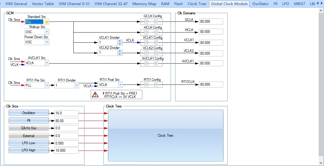
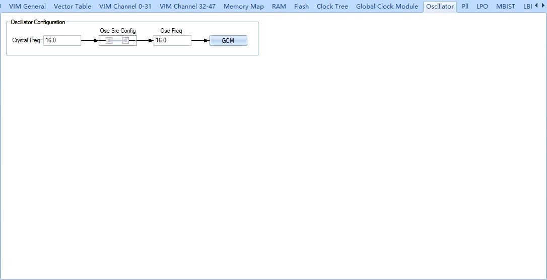
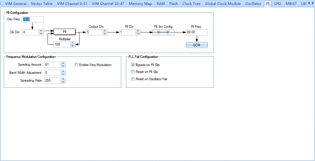
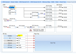
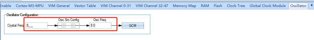
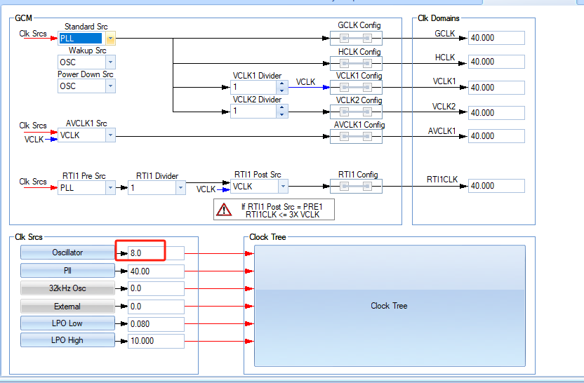
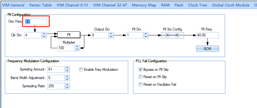
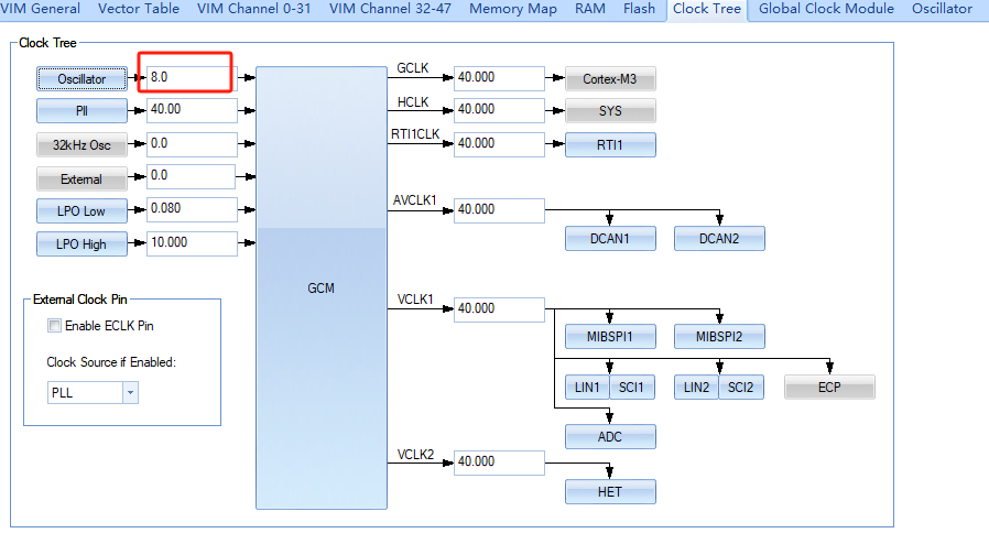
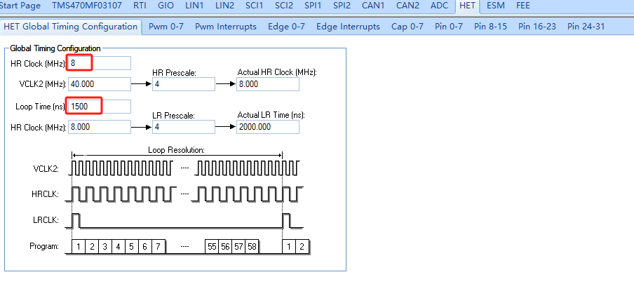
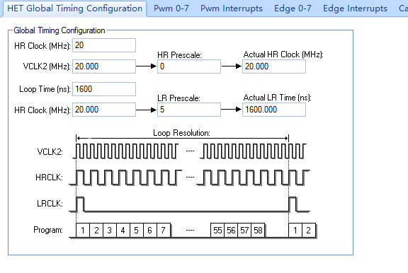
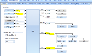
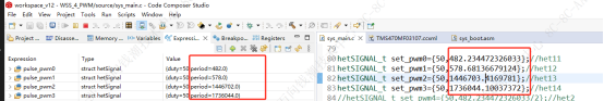
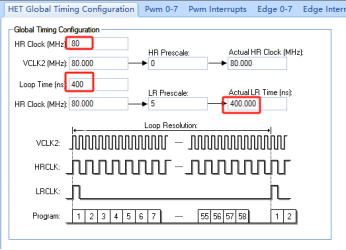
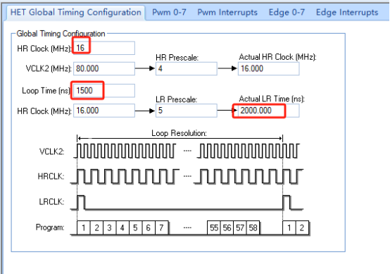
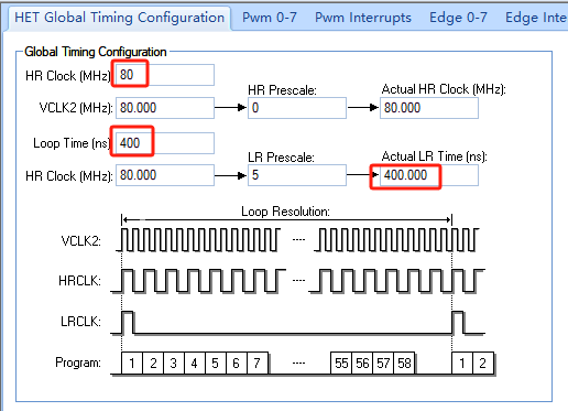
HET Global Timing Configuration is as follows:
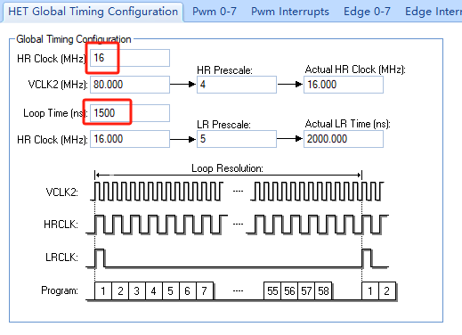
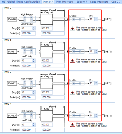
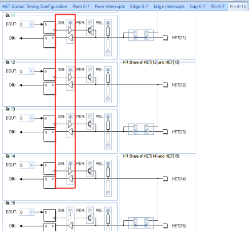
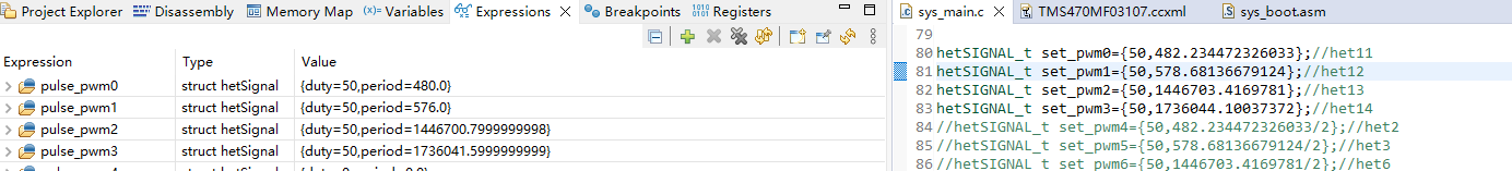
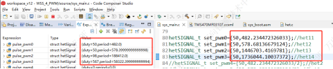
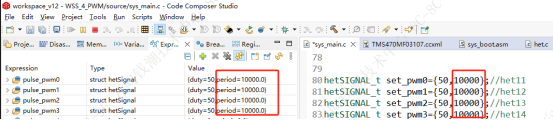
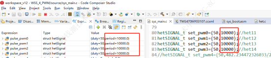
The main function is as follows:
int main(void)
{
/* USER CODE BEGIN (2) */
hetInit();
pwmSetSignal(pwm0,set_pwm0);
pwmSetSignal(pwm1,set_pwm1);
pwmSetSignal(pwm2,set_pwm2);
pwmSetSignal(pwm3,set_pwm3);
// pwmSetSignal(pwm4,set_pwm4);
// pwmSetSignal(pwm5,set_pwm5);
// pwmSetSignal(pwm6,set_pwm6);
// pwmSetSignal(pwm7,set_pwm7);
pwmStart(pwm0);
pwmStart(pwm1);
pwmStart(pwm2);
pwmStart(pwm3);
// pwmStart(pwm4);
// pwmStart(pwm5);
// pwmStart(pwm6);
// pwmStart(pwm7);
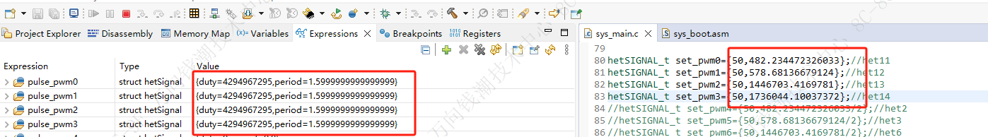
pulse_pwm0 = pwmGetSignal(pwm0);
pulse_pwm1 = pwmGetSignal(pwm1);
pulse_pwm2 = pwmGetSignal(pwm2);
pulse_pwm3 = pwmGetSignal(pwm3);
// pulse_pwm4 = pwmGetSignal(pwm4);
// pulse_pwm5 = pwmGetSignal(pwm5);
// pulse_pwm6 = pwmGetSignal(pwm6);
// pulse_pwm7 = pwmGetSignal(pwm7);
// }
/* USER CODE END */
}
4 PWM signal Period set is the same with the PWM signals generated by program,covering the minimum(482us) and maximum period(1736044us) i want.
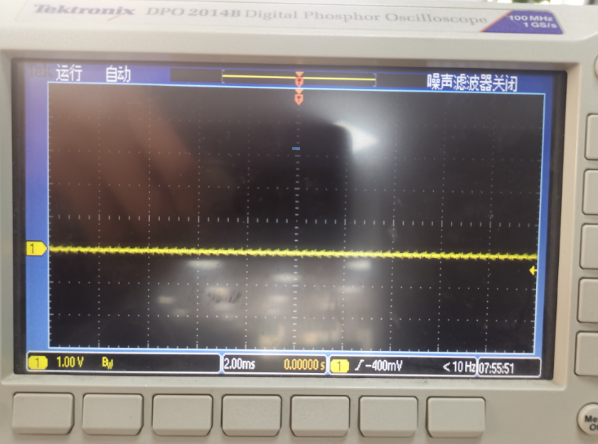
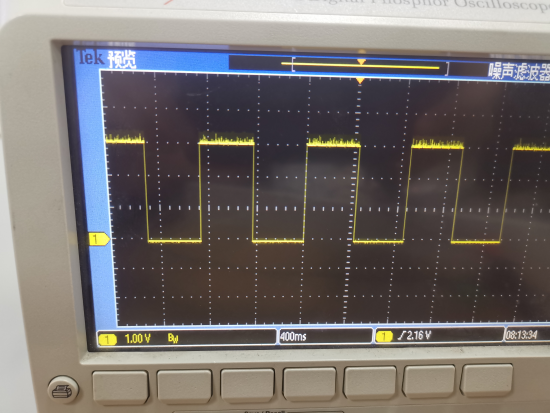
BUT the real PWM signal waves are as follows:
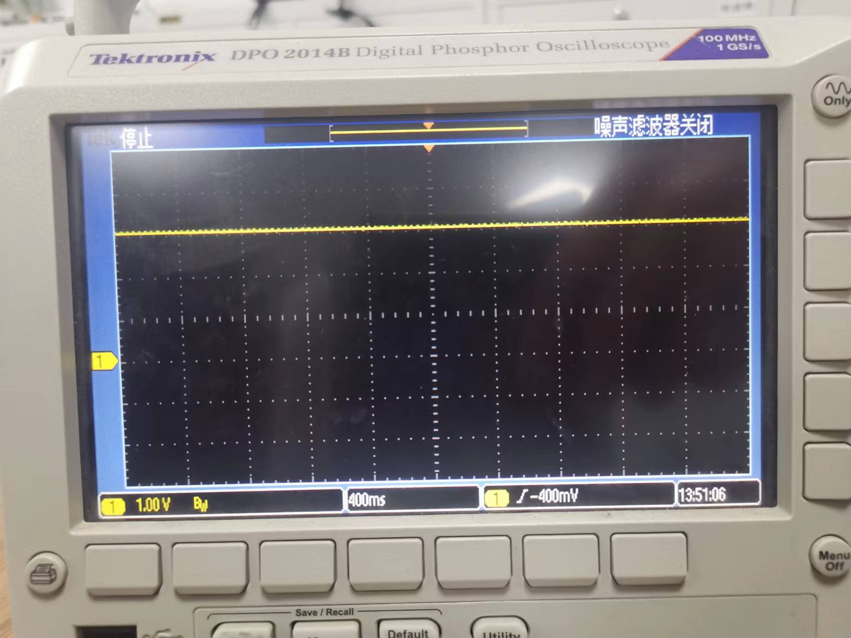
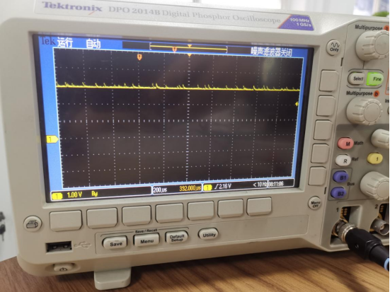
S1(PWM0,het[11]):
Constantly HIGH level:
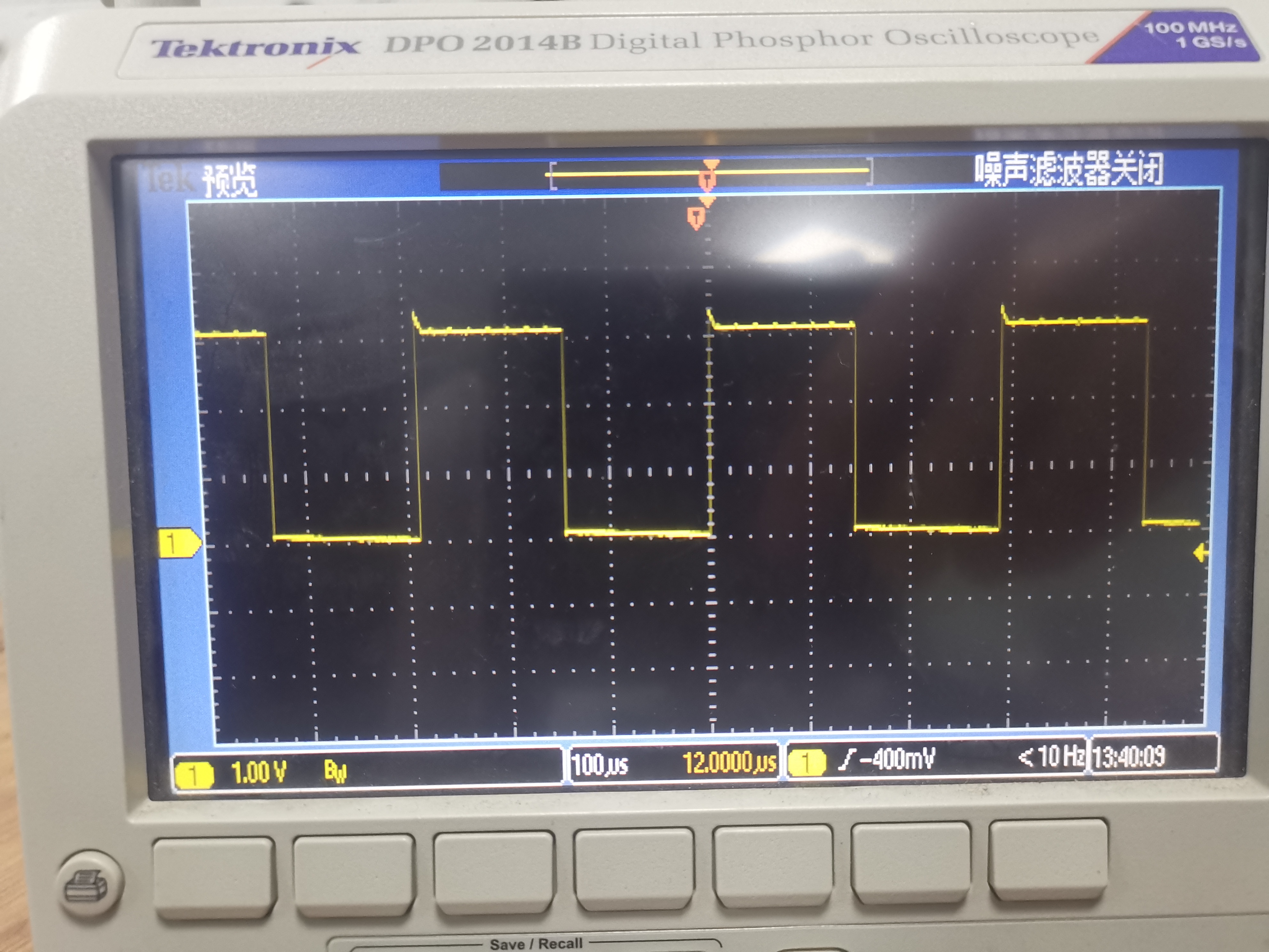
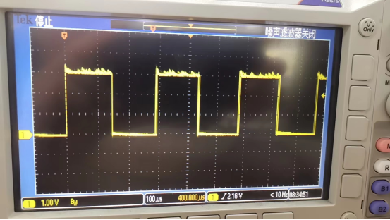
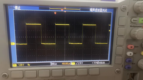
S2(PWM1,het[12]):
displayed PWM wave output period is 290us,which is HALF of the set period 578us:
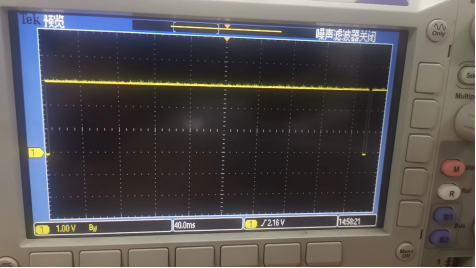
S3(PWM2,het[13]):
displayed PWM wave output period is 720ms,which is HALF of the set period 1446703us:
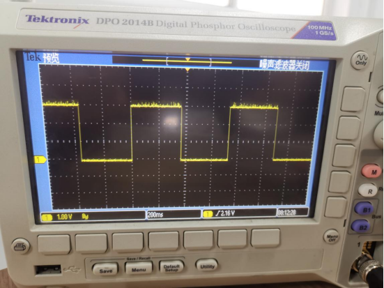
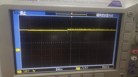
S4(PWM3,het[14]):
displayed PWM wave output period is 880ms,which is HALF of the set period 1736044us
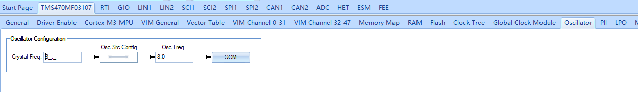
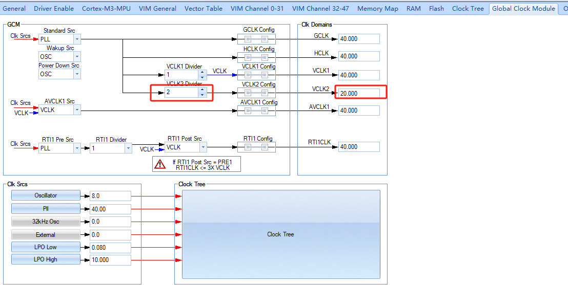
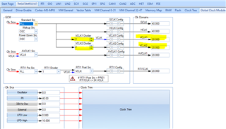
When the global timing configuration is as follows,which is default setting(other configuration stays the same):
PWM0 and PWM1 period set is the same with the program-generated value,but program-generated value of PWM2 and PWM3 duty&period are abnormal compared with the duty&period set.You can see as follows:
Oscilloscope Screen displays are as follows:
S1:period=960us,TWICE of the set period 480us
S2:period=1160us,TWICE if the set period 578us
S3:almost constant level 376ms TWICE of 188414us
S4:duty abnormal, constant HIGH level:
Here in order for simplification, some other test and description is as follows:
HET Global Timing Configuration ONE:
4 PWM signal Period set is 10000us(10ms),which is the same with the PWM signals generated:
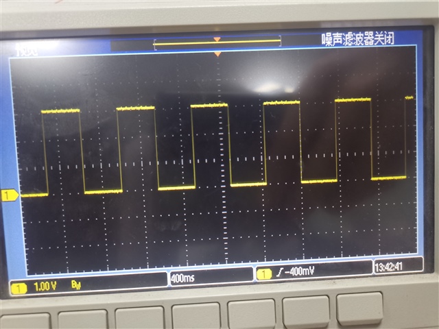
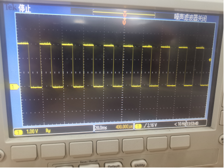
But the real PWM pulse waves are as follows:
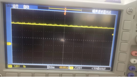
S1(PWM0,het[11]):NO PWM wave shape displayed on Oscilloscope screen,but pulled HIGH constantly.
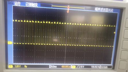
S2(PWM1,het[12]),S3(PWM2,het[13]),S4(PWM3,het[14]):PWM waves are displayed as follows on screen,but pulse period(5000us or 5ms) is HALF of the set period(10000us or 10ms):
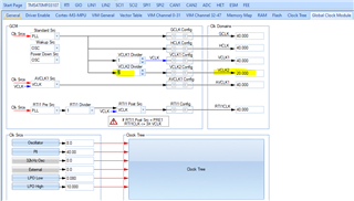
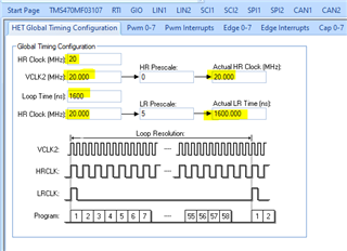
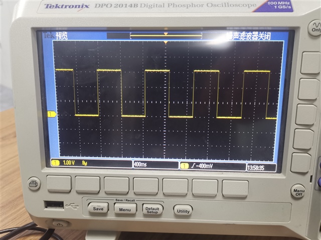
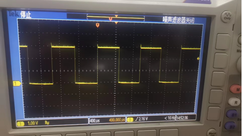
WHEN the global timing configuration TWO is as follows:
4 PWM signal Period set is 10000us(10ms),which is the same with the PWM signals generated:
But the real 4 PWM pulse waves are as follows,all having high and low level apparently,but pulse period(20000us or 20ms) is TWICE of the set period(10000us or 10ms).
All in all, I wonder, based on the certain HET timing configuration, why the generated PWM periods are not the same with the PWM period(& duty) set by me?
Could you help check this case? Thanks.
Best Regards,
Cherry