This thread has been locked.

If you have a related question, please click the "Ask a related question" button in the top right corner. The newly created question will be automatically linked to this question.

MSP432E401Y: PSU

Part Number: MSP432E401Y
Other Parts Discussed in Thread: TPS2052B

When using the MSP432E401Y ethernet launchpad with a customer-designed daughtercard, do we need to provide 5V supply to the headers if we will not use USB connectivity, besides for debugging purpose with the XDS110. I believe we only need to provide 3.3V VDD / 3.3V VDDA correct me if im wrong


Best

Dimitri

  • Hi,

      Are you talking about providing power to the daughter card? The LaunchPad has two BoosterPack interfaces and each will bring out both the 5V and 3.3V to the plug-in daughter cards. If your daughter card does not need 5V then that should be fine. 

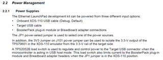
      If you are referring to supplying power to the LaunchPad main board then please refer to the user's guide as the LP can take from one of the three power sources using JP1. 

  •   If you are referring to supplying power to the LaunchPad main board

    Yes, that. For example I have buck on the board launchpad mates to.

    I see JP1 but it referring to 5V ->3.3V LDO.

    If i have a buck on the mating board generating a 3V3 rail, my understanding is i do not need 5V rail at all, correct?

    And I will provide 3V3 throught the boosterpack header connections. and 5V will float (not needed).

    Is that correct?

  • Hi,

    2.1.6.4 Other Headers and Jumpers
    JP1 is provided to select the 5-V power input source for the Ethernet LaunchPad development kit. The left
    position is for BoosterPack plug-in module power; this position also disconnects both USB voltages from
    the board’s primary 5-V input. In the left position, the TPS2052B does not limit current so additional care
    should be exercised. The middle position draws power from the USB connector on the bottom of the board
    near the Ethernet jack. The right position is the default, in which power is drawn from the XDS-110 USB
    connection through J101. If JP1 is in the left or middle position, which selects the BoosterPack headers or
    the USB OTG connector, respectively, externally provide 3.3 V to the board, and remove the 3V3 jumper
    on J101.

  • Thank you for that.

    Should we provide ext. 5V as well in addition to 3v3?
    e.g we want to use USB connection for some reason but not all the time.

  • I don't think 5V is needed unless you need USB in Host/OTG mode. In another word, for USB device mode, you don't really need VBUS which is 5V.