Other Parts Discussed in Thread: MSPM0G3507, , SYSCONFIG, UNIFLASH
Hello Texas Instruments experts,
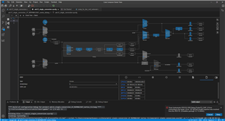
I am encountering an issue using CCS Theia IDE (Version: 1.3.1.4, Default VS Code API: 1.79.0) on Windows 11, specifically during the compilation and flashing process for the MSPM0G3507 microcontroller.
Recently, I adjusted the CPUCLK and MCLK settings to 80 MHz in order to operate the ADC at the same frequency. After this change, I started receiving the following error during the flashing phase on the LP-MSPM0G3507 board, although the IDE compiles the code without any issues:
"Texas Instruments XDS110 USB Debug Probe/CS_DAP_0 Error connecting to the target: (Error -261 @ 0x0) Invalid response was received from the XDS110. (Emulation package 12.7.0.00062)"
This error suggests a problem in communicating with the XDS110 debug probe, which did not occur before the mentioned changes. Attached are the system logs for detailed analysis.
Could you guide me on what might be causing this error and how I can resolve it? Could the change in the operating frequency of the microcontroller have influenced the communication with the debug probe?
I appreciate your help in advance and look forward to your guidance.
[0]**** Build of configuration Debug for project adc12_single_conversion_LP_MSPM0G3507_nortos_ticlang ****
[1]"C:\\ti\\ccstheia131\\ccs\\utils\\bin\\gmake" -k -j 4 all -O
[2]Building file: "../adc12_single_conversion.syscfg"
[3]Invoking: SysConfig
[4]"C:/ti/ccstheia131/ccs/utils/sysconfig_1.19.0/sysconfig_cli.bat" --script "C:/Users/verga/workspace_ccstheia/adc12_single_conversion_LP_MSPM0G3507_nortos_ticlang/adc12_single_conversion.syscfg" -o "." -s "C:/ti/mspm0_sdk_2_00_00_03/.metadata/product.json" --compiler ticlang
[5]Running script...
[6]Validating...
[7]info: /ti/project_config/ProjectConfig deviceSpin: Note: User must select a device after migration. User must make sure to select the same device as the CCS Launch Device setting for proper configuration.
[8]info: ADC12_0(/ti/driverlib/ADC12) totalConversionRate: When Power Down Mode is set to Auto, ADC wakeup time may need to be considered in each sample window. Refer to the device specific data sheet for specifications on the ADC Wakeup Time.
[9]info: TIMER_0(/ti/driverlib/TIMER): Peripheral does not retain register contents in STOP or STANDBY modes. User should take care to save and restore register configuration in application. See Retention Configuration section for more details.
[10]Generating Code (adc12_single_conversion.syscfg)...
[11]Writing C:\Users\verga\workspace_ccstheia\adc12_single_conversion_LP_MSPM0G3507_nortos_ticlang\Debug\device_linker.cmd...
[12]Writing C:\Users\verga\workspace_ccstheia\adc12_single_conversion_LP_MSPM0G3507_nortos_ticlang\Debug\device.opt...
[13]Writing C:\Users\verga\workspace_ccstheia\adc12_single_conversion_LP_MSPM0G3507_nortos_ticlang\Debug\device.cmd.genlibs...
[14]Writing C:\Users\verga\workspace_ccstheia\adc12_single_conversion_LP_MSPM0G3507_nortos_ticlang\Debug\ti_msp_dl_config.c...
[15]Writing C:\Users\verga\workspace_ccstheia\adc12_single_conversion_LP_MSPM0G3507_nortos_ticlang\Debug\ti_msp_dl_config.h...
[16]Writing C:\Users\verga\workspace_ccstheia\adc12_single_conversion_LP_MSPM0G3507_nortos_ticlang\Debug\Event.dot...
[17]Finished building: "../adc12_single_conversion.syscfg"
[18]Building file: "../adc12_single_conversion.c"
[19]Invoking: Arm Compiler
[20]"C:/ti/ccstheia131/ccs/tools/compiler/ti-cgt-armllvm_3.2.1.LTS/bin/tiarmclang.exe" -c @"device.opt" -march=thumbv6m -mcpu=cortex-m0plus -mfloat-abi=soft -mlittle-endian -mthumb -O2 -I"C:/Users/verga/workspace_ccstheia/adc12_single_conversion_LP_MSPM0G3507_nortos_ticlang" -I"C:/Users/verga/workspace_ccstheia/adc12_single_conversion_LP_MSPM0G3507_nortos_ticlang/Debug" -I"C:/ti/mspm0_sdk_2_00_00_03/source/third_party/CMSIS/Core/Include" -I"C:/ti/mspm0_sdk_2_00_00_03/source" -gdwarf-3 -MMD -MP -MF"adc12_single_conversion.d_raw" -MT"adc12_single_conversion.o" @"./device.opt" -o"adc12_single_conversion.o" "../adc12_single_conversion.c"
[21]Finished building: "../adc12_single_conversion.c"
[22]Building file: "C:/ti/mspm0_sdk_2_00_00_03/source/ti/devices/msp/m0p/startup_system_files/ticlang/startup_mspm0g350x_ticlang.c"
[23]Invoking: Arm Compiler
[24]"C:/ti/ccstheia131/ccs/tools/compiler/ti-cgt-armllvm_3.2.1.LTS/bin/tiarmclang.exe" -c @"device.opt" -march=thumbv6m -mcpu=cortex-m0plus -mfloat-abi=soft -mlittle-endian -mthumb -O2 -I"C:/Users/verga/workspace_ccstheia/adc12_single_conversion_LP_MSPM0G3507_nortos_ticlang" -I"C:/Users/verga/workspace_ccstheia/adc12_single_conversion_LP_MSPM0G3507_nortos_ticlang/Debug" -I"C:/ti/mspm0_sdk_2_00_00_03/source/third_party/CMSIS/Core/Include" -I"C:/ti/mspm0_sdk_2_00_00_03/source" -gdwarf-3 -MMD -MP -MF"startup_mspm0g350x_ticlang.d_raw" -MT"startup_mspm0g350x_ticlang.o" @"./device.opt" -o"startup_mspm0g350x_ticlang.o" "C:/ti/mspm0_sdk_2_00_00_03/source/ti/devices/msp/m0p/startup_system_files/ticlang/startup_mspm0g350x_ticlang.c"
[25]Finished building: "C:/ti/mspm0_sdk_2_00_00_03/source/ti/devices/msp/m0p/startup_system_files/ticlang/startup_mspm0g350x_ticlang.c"
[26]Building file: "ti_msp_dl_config.c"
[27]Invoking: Arm Compiler
[28]"C:/ti/ccstheia131/ccs/tools/compiler/ti-cgt-armllvm_3.2.1.LTS/bin/tiarmclang.exe" -c @"device.opt" -march=thumbv6m -mcpu=cortex-m0plus -mfloat-abi=soft -mlittle-endian -mthumb -O2 -I"C:/Users/verga/workspace_ccstheia/adc12_single_conversion_LP_MSPM0G3507_nortos_ticlang" -I"C:/Users/verga/workspace_ccstheia/adc12_single_conversion_LP_MSPM0G3507_nortos_ticlang/Debug" -I"C:/ti/mspm0_sdk_2_00_00_03/source/third_party/CMSIS/Core/Include" -I"C:/ti/mspm0_sdk_2_00_00_03/source" -gdwarf-3 -MMD -MP -MF"ti_msp_dl_config.d_raw" -MT"ti_msp_dl_config.o" @"./device.opt" -o"ti_msp_dl_config.o" "ti_msp_dl_config.c"
[29]Finished building: "ti_msp_dl_config.c"
[30]Building target: "adc12_single_conversion_LP_MSPM0G3507_nortos_ticlang.out"
[31]Invoking: Arm Linker
[32]"C:/ti/ccstheia131/ccs/tools/compiler/ti-cgt-armllvm_3.2.1.LTS/bin/tiarmclang.exe" @"device.opt" -march=thumbv6m -mcpu=cortex-m0plus -mfloat-abi=soft -mlittle-endian -mthumb -O2 -gdwarf-3 -Wl,-m"adc12_single_conversion_LP_MSPM0G3507_nortos_ticlang.map" -Wl,-i"C:/ti/mspm0_sdk_2_00_00_03/source" -Wl,-i"C:/Users/verga/workspace_ccstheia/adc12_single_conversion_LP_MSPM0G3507_nortos_ticlang" -Wl,-i"C:/Users/verga/workspace_ccstheia/adc12_single_conversion_LP_MSPM0G3507_nortos_ticlang/Debug/syscfg" -Wl,-i"C:/ti/ccstheia131/ccs/tools/compiler/ti-cgt-armllvm_3.2.1.LTS/lib" -Wl,--diag_wrap=off -Wl,--display_error_number -Wl,--warn_sections -Wl,--xml_link_info="adc12_single_conversion_LP_MSPM0G3507_nortos_ticlang_linkInfo.xml" -Wl,--rom_model -o "adc12_single_conversion_LP_MSPM0G3507_nortos_ticlang.out" "./adc12_single_conversion.o" "./ti_msp_dl_config.o" "./startup_mspm0g350x_ticlang.o" -Wl,-l"./device_linker.cmd" -Wl,-ldevice.cmd.genlibs -Wl,-llibc.a
[33]warning #10210-D: creating ".sysmem" section with default size of 0x800; use the -heap option to change the default size
[34]Finished building target: "adc12_single_conversion_LP_MSPM0G3507_nortos_ticlang.out"
[35]**** Build Finished ****
/**
 * These arguments were used when this file was generated. They will be automatically applied on subsequent loads
 * via the GUI or CLI. Run CLI with '--help' for additional information on how to override these arguments.
 * @cliArgs --device "MSPM0G350X" --package "LQFP-64(PM)" --part "Default" --product "mspm0_sdk@2.00.00.04"
 * @versions {"tool":"1.19.0+3426"}
 */

/**
 * Import the modules used in this configuration.
 */
const ADC12  = scripting.addModule("/ti/driverlib/ADC12", {}, false);
const ADC121 = ADC12.addInstance();
const Board  = scripting.addModule("/ti/driverlib/Board");
const COMP   = scripting.addModule("/ti/driverlib/COMP", {}, false);
const COMP1  = COMP.addInstance();
const GPIO   = scripting.addModule("/ti/driverlib/GPIO", {}, false);
const GPIO1  = GPIO.addInstance();
const GPIO2  = GPIO.addInstance();
const GPIO3  = GPIO.addInstance();
const SYSCTL = scripting.addModule("/ti/driverlib/SYSCTL");
const TIMER  = scripting.addModule("/ti/driverlib/TIMER", {}, false);
const TIMER1 = TIMER.addInstance();

/**
 * Write custom configuration values to the imported modules.
 */
const divider7       = system.clockTree["PLL_PDIV"];
divider7.divideValue = 2;

const divider9       = system.clockTree["UDIV"];
divider9.divideValue = 2;

const multiplier2         = system.clockTree["PLL_QDIV"];
multiplier2.multiplyValue = 5;

const mux3       = system.clockTree["EXCLKMUX"];
mux3.inputSelect = "EXCLKMUX_LFCLK";

const mux6       = system.clockTree["FCCSELCLKMUX"];
mux6.inputSelect = "FCCSELCLKMUX_SYSOSC";

const mux8       = system.clockTree["HSCLKMUX"];
mux8.inputSelect = "HSCLKMUX_SYSPLL2X";

ADC121.$name                      = "ADC12_0";
ADC121.adcMem0chansel             = "DL_ADC12_INPUT_CHAN_2";
ADC121.enabledInterrupts          = ["DL_ADC12_INTERRUPT_MEM0_RESULT_LOADED"];
ADC121.powerDownMode              = "DL_ADC12_POWER_DOWN_MODE_MANUAL";
ADC121.sampClkSrc                 = "DL_ADC12_CLOCK_ULPCLK";
ADC121.sampleTime0                = "25 ns";
ADC121.peripheral.$assign         = "ADC0";
ADC121.peripheral.adcPin2.$assign = "PA25";
ADC121.adcPin2Config.$name        = "ti_driverlib_gpio_GPIOPinGeneric0";


COMP1.$name                          = "COMP";
COMP1.channelEnable                  = ["NEG"];
COMP1.vSource                        = "DL_COMP_REF_SOURCE_VREF_DAC";
COMP1.enableOutputFilter             = true;
COMP1.enabledInterrupts              = ["DL_COMP_INTERRUPT_OUTPUT_EDGE"];
COMP1.controlSelect                  = "DL_COMP_DAC_CONTROL_SW";
COMP1.peripheral.$assign             = "COMP0";
COMP1.peripheral.compPinNeg0.$assign = "PA27";
COMP1.compPinNeg0Config.$name        = "ti_driverlib_gpio_GPIOPinGeneric1";

GPIO1.$name                          = "GPIO_LEDS";
GPIO1.port                           = "PORTA";
GPIO1.portSegment                    = "Upper";
GPIO1.associatedPins[0].$name        = "USER_LED_1";
GPIO1.associatedPins[0].initialValue = "SET";
GPIO1.associatedPins[0].assignedPin  = "18";
GPIO1.associatedPins[0].pin.$assign  = "PA18";

GPIO2.$name                                 = "GPIO_LED";
GPIO2.associatedPins[0].$name               = "USER_LED_2";
GPIO2.associatedPins[0].initialValue        = "SET";
GPIO2.associatedPins[0].assignedPort        = "PORTA";
GPIO2.associatedPins[0].assignedPortSegment = "Lower";
GPIO2.associatedPins[0].assignedPin         = "1";
GPIO2.associatedPins[0].pin.$assign         = "PA1";

GPIO3.$name                                 = "GPIO_RESET";
GPIO3.associatedPins[0].$name               = "USER_RESET";
GPIO3.associatedPins[0].initialValue        = "SET";
GPIO3.associatedPins[0].assignedPort        = "PORTA";
GPIO3.associatedPins[0].assignedPortSegment = "Lower";
GPIO3.associatedPins[0].assignedPin         = "2";
GPIO3.associatedPins[0].pin.$assign         = "PA2";

SYSCTL.forceDefaultClkConfig = true;
SYSCTL.clockTreeEn           = true;
SYSCTL.MFPCLKEn              = true;
SYSCTL.MFPCLKSource          = "HFCLK";
SYSCTL.HFCLK4MFPCLKDIV       = "2";
SYSCTL.HFCLK_Freq            = 8000000;

TIMER1.$name               = "TIMER_0";
TIMER1.timerMode           = "PERIODIC";
TIMER1.enableRepeatCounter = true;
TIMER1.repeatCounter       = 4;
TIMER1.interrupts          = ["REPC"];
TIMER1.interruptPriority   = "0";
TIMER1.timerPeriod         = "250 us";
TIMER1.peripheral.$assign  = "TIMA0";

const VREF                  = scripting.addModule("/ti/driverlib/VREF", {}, false);
VREF.vrefPosPinConfig.$name = "ti_driverlib_gpio_GPIOPinGeneric2";

/**
 * Pinmux solution for unlocked pins/peripherals. This ensures that minor changes to the automatic solver in a future
 * version of the tool will not impact the pinmux you originally saw.  These lines can be completely deleted in order to
 * re-solve from scratch.
 */
Board.peripheral.$suggestSolution           = "DEBUGSS";
Board.peripheral.swclkPin.$suggestSolution  = "PA20";
Board.peripheral.swdioPin.$suggestSolution  = "PA19";
VREF.peripheral.$suggestSolution            = "VREF";
VREF.peripheral.vrefPosPin.$suggestSolution = "PA23";
/**************************************************************************************************
 * Descrição:
 * Este programa demonstra a aplicação de um comparador interno no microcontrolador MSPM0G3507
 * para monitorar sinais analógicos em sistemas críticos, como aqueles encontrados em aplicações
 * de engenharia nuclear. Utilizando um DAC configurável, o sistema é capaz de detectar e contar
 * eventos de transição que ultrapassam um limiar estabelecido. A periodicidade do monitoramento é
 * controlada por um timer embutido, e o estado de LEDs é usado para fornecer uma indicação visual
 * imediata dos eventos detectados. Este sistema é projetado para oferecer precisão e confiabilidade
 * em medições e monitoramento em ambientes controlados de alta segurança.
 *
 * Especificações Técnicas:
 * - Microcontrolador: MSPM0G3507
 * - IDE: Code Composer Studio (CCS)
 * - Versão da IDE: Texas Instruments Code Composer Studio Theia Version: 1.3.1.4
 * - API Padrão do VS Code: 1.79.0
 * - Versão do Compilador: TI v20.2.5.LTS
 * - Configuração do Hardware:
 *   - Comparador: Pino PA27
 *   - LED 1: Pino PA00
 *   - LED 2: Pino PA01
 *   - VREF+: Pino PA23 (desconectado nos testes)
 *
 * Autores: Diego, Adelson, Ubaldo
 * Data: 16/04/2024
 *
 * Funcionalidades:
 * 1. Configuração do comparador interno com um DAC para ajuste de limiar de detecção.
 * 2. Uso de timer integrado para regular intervalos de monitoramento.
 * 3. Contagem e registro de eventos que excedem o limiar especificado.
 * 4. Indicação visual através de LEDs para cada evento detectado.
 * 5. Implementação focada em aplicações de alta segurança e precisão, típicas em cenários de
 *    engenharia nuclear.
 **************************************************************************************************/

#include <stdio.h>
#include <stdint.h>
#include <string.h>
#include "ti/driverlib/dl_timera.h"
#include "ti_msp_dl_config.h"
#include <sys/_stdint.h>

// Definições de tensão de referência e tensão de saída para o DAC do comparador
#define COMP_INST_REF_VOLTAGE_mV (1400)
#define COMP_INST_DAC8_OUTPUT_VOLTAGE_mV (500)

#define NUM_AMOSTRAS 1000                      // Números de amostras

// Variáveis globais para contagem de eventos e controle
volatile uint16_t counterTimer = 0;                 // Contador de tempo baseado em interrupção de timer
volatile uint32_t contador_1 = 0;                   // Contador de eventos de borda de subida
volatile uint32_t counterADC = 0;
volatile uint16_t gAdcResult = 0;

volatile bool gCheckADC;
volatile bool start = false;                        // Flag para iniciar a contagem de eventos

uint8_t dacValue;                                   // Valor para configurar o DAC
uint32_t varTimer = 1000;                              // Intervalo de tempo para a contagem de eventos
uint32_t contadorBuff = 0;                          // Buffer para armazenar o valor do contador durante o processamento

uint16_t sampleCount = 0;                       // Variável de contagem
uint16_t amostras[NUM_AMOSTRAS];                // Array para armazenar as amostras
uint16_t adcArray[4096] = {0};                                                                   // Array para contar as ocorrências de cada valor ADC

//-----------------------------------------------------------------------------------------------------------
void salvarAmostrasCSV(const char *nomeArquivo, uint16_t amostras[], int numAmostras) {
    // Construa o caminho absoluto
    const char *caminhoAbsoluto = "C:/Users/verga/OneDrive/Desktop/ADC_resultados/abril/amostra.csv";

    FILE *file = fopen(caminhoAbsoluto, "w");

    if (file == NULL){
        printf("Erro ao abrir o arquivo.\n");
        return;
    }

    /*fprintf(file, "Valor ADC,Ocorrencias\n");
    for(int i = 0; i < 4096; i++){
        fprintf(file, "%d,%d\n", i, adcArray[i]);
    }*/

    fprintf(file, "Amostra\n");
    for(int i = 0; i < numAmostras; i++){
        fprintf(file, " %d\n", amostras[i]);
    }

    fclose(file);
}

//-----------------------------------------------------------------------------------------------------------------------------
// Função para limpar array
void limparArray(uint16_t array[], int tamanho) {
    memset(array, 0, tamanho * sizeof(uint16_t));
}

//-----------------------------------------------------------------------------------------------------------
void adc () {
    start = false;                                                              // Vesliga COMP
    DL_ADC12_startConversion(ADC12_0_INST);
    gAdcResult = DL_ADC12_getMemResult(ADC12_0_INST, DL_ADC12_MEM_IDX_0) & 0xFFF;
    //printf("%d \n", gAdcResult);
    amostras[sampleCount] = gAdcResult;                                         // Armazena a amostra no array
    sampleCount++;                                                              // Incrementa a contagem de amostras
    gCheckADC = false;                                                          // Reinicia a flag para próxima amostra
    DL_ADC12_enableConversions(ADC12_0_INST);
    counterADC++;
    //printf("%d \n", counterADC);
    start = true;                                                              // Liga COMP
}

//-----------------------------------------------------------------------------------------------------------
void ADC12_0_INST_IRQHandler(void) {
    switch (DL_ADC12_getPendingInterrupt(ADC12_0_INST)) {
        case DL_ADC12_IIDX_MEM0_RESULT_LOADED:
            gCheckADC = true;
            break;
        default:
            break;
    }
}

//-----------------------------------------------------------------------------------------------------------------------------
// Tratador de interrupção para o Timer
void TIMER_0_INST_IRQHandler(void) {
    if (DL_TimerA_getPendingInterrupt(TIMER_0_INST) == DL_TIMERA_IIDX_REPEAT_COUNT) {
        counterTimer++;                                                 // Incrementa o contador de tempo a cada interrupção do timer
        //DL_GPIO_togglePins(GPIO_LEDS_PORT, GPIO_LEDS_USER_LED_1_PIN);
    }
}

//-----------------------------------------------------------------------------------------------------------------------------
// Tratador de interrupção para o grupo de interrupções do comparador
void GROUP1_IRQHandler(void) {

    if (DL_COMP_getPendingInterrupt(COMP_INST) == DL_COMP_IIDX_OUTPUT_EDGE_INV) {   // Verifica se a interrupção foi causada por uma borda de subida
        if (!start) {
            start = true;                                                       // Define a flag de início se ainda não estiver setada
        }
        DL_GPIO_togglePins(GPIO_LEDS_PORT, GPIO_LEDS_USER_LED_1_PIN);           // Alterna o estado do LED (ver Comparador osciloscópio)
        contador_1++;                                                           // Incrementa o contador de bordas de subida
        adc();
        //printf("%d \n", contador_1);
    }
/*
    if (DL_COMP_getPendingInterrupt(COMP_INST) == DL_COMP_IIDX_OUTPUT_EDGE) {   // Verifica se a interrupção foi causada por uma borda de subida
        if (!start) {
            start = true;                                                       // Define a flag de início se ainda não estiver setada
        }
        DL_GPIO_togglePins(GPIO_LEDS_PORT, GPIO_LEDS_USER_LED_1_PIN);           // Alterna o estado do LED (ver Comparador osciloscópio)
        contador_1++;                                                           // Incrementa o contador de bordas de subida
        //adc();
        //printf("%d \n", contador_1);
    }
    */
}

//-----------------------------------------------------------------------------------------------------------------------------
// Configura o comparador e habilita o DAC e interrupções relacionadas
void confCOMP () {
    dacValue = (COMP_INST_DAC8_OUTPUT_VOLTAGE_mV * 255) / COMP_INST_REF_VOLTAGE_mV;     // Calcula o valor do DAC baseado na tensão configurada
    DL_COMP_setDACCode0(COMP_INST, dacValue);                                           // Configura o DAC do comparador
    DL_COMP_enable(COMP_INST);                                                          // Habilita o comparador
    NVIC_EnableIRQ(COMP_INST_INT_IRQN);                                                 // Habilita interrupções do comparador
}

//-----------------------------------------------------------------------------------------------------------------------------
void confTIMER () {
    DL_TimerA_startCounter(TIMER_0_INST);                       // Inicia o contador do timer
}

//-----------------------------------------------------------------------------------------------------------------------------
int main(void) {
    SYSCFG_DL_init();
    //DL_GPIO_setPins(GPIO_LEDS_PORT, GPIO_LEDS_USER_LED_1_PIN);
    limparArray(amostras, NUM_AMOSTRAS);

    NVIC_EnableIRQ(TIMER_0_INST_INT_IRQN);                          // Habilita as interrupções do timer
    NVIC_EnableIRQ(ADC12_0_INST_INT_IRQN);
    gCheckADC = false;

    confCOMP();                                                   // Configura e habilita o comparador
    confTIMER();

    while(1) {
        contadorBuff = 0;                                           // Reseta o buffer de contador
        while (!start);                                             // Aguarda até que a flag de início seja setada
        DL_TimerA_startCounter(TIMER_0_INST);                       // Inicia o contador do timer
        while (counterTimer < varTimer);                            // Aguarda o período de tempo especificado

        contadorBuff = contador_1;                                  // Armazena o valor do contador em buffer
        printf("%d  \t %d \t %d \n", contador_1, contadorBuff, counterADC);
        start = false;                                              // Reseta a flag de início
        contador_1 = 0;                                             // Reseta o contador de eventos
        counterTimer = 0;                                           // Reseta o contador de tempo
    }
    return 0;


        //contadorBuff = 0;                                           // Reseta o buffer de contador
    //while (!start);                                             // Aguarda até que a flag de início seja setada


    //while (1) {
        //while (counterTimer < varTimer);                            // Aguarda o período de tempo especificado
    //}
    //while (counterTimer < varTimer);                            // Aguarda o período de tempo especificado
    /*

    //contadorBuff = contador_1;                                  // Armazena o valor do contador em buffer
    //printf("%d  \t %d \t %d \n", contador_1, contadorBuff, counterADC);
    start = false;                                              // Reseta a flag de início
    contador_1 = 0;                                             // Reseta o contador de eventos
    counterTimer = 0;                                           // Reseta o contador de tempo
    counterADC = 0;
    //start = false;                                              // Reseta a flag de início

    printf("Antes de salvar CSV\n");
    salvarAmostrasCSV("amostras.csv", amostras, NUM_AMOSTRAS);
    printf("Depois de salvar CSV\n");
    limparArray(amostras, NUM_AMOSTRAS);

    //DL_GPIO_clearPins(GPIO_LEDS_PORT, GPIO_LEDS_USER_LED_1_PIN);
    return 0;  */
}