This thread has been locked.

If you have a related question, please click the "Ask a related question" button in the top right corner. The newly created question will be automatically linked to this question.

AM263P4: mcan_external_read_write example does not output CAN messages on AM263Px-CC

Part Number: AM263P4
Other Parts Discussed in Thread: TCA6424, TMDSCNCD263P, SYSCONFIG

Tool/software:

I am working with the AM263Px-cc on a proof of concept project, and I am currently trying to get the mcan peripheral working.

I have loaded the mcan_external_read_write example project from MCU+ SDK for AM263Px - 09.02.00.55. 

I have updated the syscfg to set the mcan peripheral to CAN4 to take advantage of the CAN transceiver on the control card.  The project builds successfully and I am able to enter debug mode as expected.

However, I am unable to see any CAN data transmitted out of the 3 pin CAN header (J5).  Stepping through the code, I can see where it calls commands to transmit, but nothing is seen at J5.

I have also used my oscilloscope to monitor R172, which is a jumper resistor from the CAN4 Tx pin of the AM263Px going into the TCAN1043ADYYRQ1 CAN Transceiver. That line is held high, and no change is seen when CAN Transmissions should be occurring.

  • Hi Nathan,

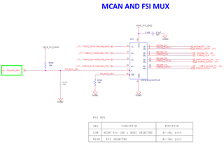
    The MCAN4 signals go through a high speed MUX before routing to the TCAN1043A transceiver. By default, MCAN is not selected:

    The FSI_MUX_SEL net must be pulled low to select the MCAN4 signals.

    Regards,

    Brennan

  • It appears that the FSI_MUX_SEL is driven by the TCA6424ARGJR, which is controlled via I2C. Therefore I've got to get that part up and communicating in order to get CAN4 and the CAN transceiver working. I saw something like this going on in the code for the AM263x example, but unfortunately that same example code isn't available for the AM263Px.

  • Nathan,

    The mcan_transciever.c file in mcu_plus_sdk_am263px_09_02_00_56\examples\drivers\mcan\mcan_external_read_write\am263px-cc\r5fss0-0_freertos contains a function to set the TCA6424 IO Expander.

    Regards,

    Brennan

  • I have made adjustments to the project to verify the following:

    - MCAN4 is selected using pins G1 and J2

    - I2C2 is selected using pins C7 and B7

    - The mcan_transceiver.c file is present in the project and its functions being called.

    - Voltage on Pin 1 of U33 (the mux mentioned earlier) is always low.

    - Voltage on Pin 7 of U33 (the MCAN4_TXD connection between the AM263Px and the mux) changes from low to high after entering debug and hitting the resume button. No other rising or falling edges are detected after the initial change from low to high.

    This still does not appear to be transmitting a CAN message on CAN4.

  • Nathan,

    I re-created your setup and am observing similar behavior. I am adding the MCAN software expert to this thread to assist at this time.

    Regards,

    Brennan

  • Hello Nathan,
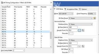
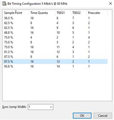
    Looks like the MCAN side setup is working as expected, which makes me think the issue is with the PCAN bus configuration. Can you confirm if the bit timing parameters as seen from PCAN View are as follows:

    Clock = 80Mhz

    Nominal Bit rate = 1000 kbps

    Nominal Bit Rate sampling point = 85%

    Data Bit Rate = 5000 kbps

    Data Bit Rate sampling point = 87.5%

    Regards,
    Aswathi

  • Nathan, 

    Can you remove the jumper on J21 and try again? The TCAN1043A needs a high signal on the wake pin in order to be operational.

  • Removing the J21 jumper did not yield any change to the behavior of the CAN4 TX pin J2.

    Aswathi, how do I reach the PCAN views you are showing?

  • Nathan,
    What is the external CAN bus used in your setup? I assumed it was PCAN-USB tool as mentioned in SDK documentation.

  • I am using an Ixxat USB-to-CAN V2 as my CAN interface, and its associated canAnalyser3 Mini program to monitor for any CAN messages. It is configured for a clock rate of 1Mhz. I have CAN high connected to pin 1 of J5, CAN low connected to pin 3 of J5, and have a terminating resistor at the input of my Ixxat USB-to-CAN interface. I have validated that this setup is working correctly on other CAN devices.

    As mentioned before, no CAN message is ever seen at Pin 7 of U33 (the CAN tx input to the Mux), the level changes from low to high one time when the resume button is clicked in debug mode. This leads me to believe that this is NOT an issue with the external CAN interface. I am able to generate CAN messages on the Ixxat USB-to-CAN and see them arrive at pins 12 and 13 of U29 (CAN transceiver) but nothing ever arrives at pin 1 of U29 (tx pin of CAN transceiver) or is sent from pin 4 of U29 (Rx pin of CAN transceiver)

    This seems to be to a configuration issue associated with the AM263Px MCAN peripherals interfacing with the external components on the TMDSCNCD263P ControlCard.

  • Hi Nathan,
    If you have made any changes to the SDK project, can you attach it here as a zip file? 

  • This project is for am263px-lp board, it won't work on CC as the transceiver file is different for both the boards.

  • This was the project that was downloaded from the Resource Explorer, MCU+ SDK for AM263Px - 09.02.00.55, Examples, Development Tools, drivers, mcan, mcan_external_read_write, r5fss0-0_nortos. I did not want the project for the LP board, but this is the only thing available for the am263px. 

    please provide links, files, or workarounds to get this working on the TMDSCNCD263P control card.

  • Please download the 09.02 SDK from ti.com: MCU-PLUS-SDK-AM263PX Software development kit (SDK) | TI.com
    You can find the documentation link in the same page.
    Once setup is done as per the doc, you can directly build and run the mcan_external_read_write project for am263px-cc.
    Let me know if that works.

    Thanks,
    Aswathi

  • downloading and using the latest SDK appears to work. To summarize:

    Using the Resource Explorer in Code Composer Studio defaulted to version 09.02.00.55 which IS NOT COMPATIBLE with the TMDSCNCD263P control card.

    Downloading the latest SDK, version 09.02.00.56, works correctly.

    One last thing. Is there a spreadsheet or tool that helps me set the correct values for CAN to achieve 500K and 250K baud rates, not using CAN FD?

  • I was able to get a message to send out at 500K through changing things in sysconfig.  However, there is still one last thing that I'm struggling to understand.  What is the relationship between the nominal bit rate and the data bit rate? I haven't been able to find anything in the documentation that clarifies the difference between the two and if there is any relationship between the two.

  • Hello Nathan,

    When operating in CAN-FD mode, different data rates are used during the arbitration phase and data phase of each CAN frame. During the arbitration phase, multiple nodes may be transmitting on the bus simultaneously. During this phase, there are several factors that limit the maximum achievable data rate of the system, so this is generally around 500kbps max. During the data phase, only one device is transmitting on the bus so a higher data rate may be used. This data phase is where CAN-FD rates of up to 12Mbps are utilized. Additional information is available in the Bosch CANFD Specification and the following document: https://www.bosch-semiconductors.com/media/ip_modules/pdf_2/papers/icc14_2013_paper_hartwich_1.pdf

    Nominal Bit Rate = Bit Rate during Arbitration phase

    Data Bit Rate = Bit Rate during Data phase

    Best Regards,

    Zackary Fleenor