This thread has been locked.
If you have a related question, please click the "Ask a related question" button in the top right corner. The newly created question will be automatically linked to this question.
Tool/software:
Hi MSPM0L1306 Champ !
A customer would like to use ADC feature of MSPM0L1306 along with AM62x.
Can you please answer toward questiosn below?
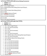
1. Please tell me which of the 16 pins of MSPM0L1306 are required to be connected and which are not.
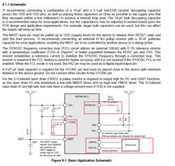
2. they ask if the peripheral circuitry (power capacitor capacity, etc.) can be used according to (MCU099_LP-MSPM0L1306 with PCB.pdf).
3. if they want to connect a debugger, can they just connect SWDIO, SWCLK two wires with AM62 MCU or do they need other wires?
They attached the spreadsheet regarding above question. Please check the attachment. then fill the your comments about interface with AM62x.
Thanks.
Best Regards,
Jack
Hi Jack,
1,2. The minimum system schematic could refer to MSPM0L1306 datasheet 9.1.1:
3. SWDIO, SWCLK, GND are necessary pins to be connected debugger (XDS110 or J-link)
Regards,
Pengfei
Hi Pengfei
Thanks for your quick response.
Can you also please let us know SWDIO, SWCLK, GND coneection for XDS110?
It's confused when we check the XDS110 user guide.
We prepared the initial connection btw MSPM0 JTAG connector and XDS110.
Can you please double check especiially for SWDIO, SWCLK, GND?
Thanks.
Regards,
Jack
Hi Jack,
It seems that your XDS110 user guide version is not as the same as my side.
Actually you could just refer the text label in your XDS110 hardware. It shows each pin name of the interface. And you just need to connect SWDIO, SWCLK and GND to MSPM0.
By the way, though XDS100 support both SWD and JTAG, MSPM0 devices only support SWD for debugging. So you only need to focus on SWD pins or function of XDS110.
Regards,
Pengfei