This thread has been locked.

If you have a related question, please click the "Ask a related question" button in the top right corner. The newly created question will be automatically linked to this question.

MSPM0L2228: EEPROM style memory storage

Part Number: MSPM0L2228
Other Parts Discussed in Thread: MSPM0G3507,

Tool/software:

Hi Ankush,

Just need to clarify please, do you mean <sdk version>\examples\nortos\LP_MSPM0G3507\eeprom should work on the MSPM0L2228 unaltered?

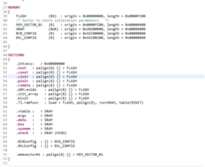
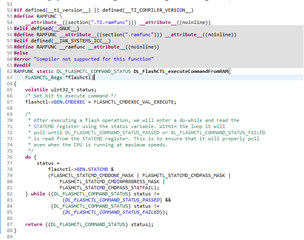
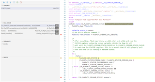
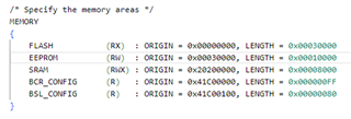
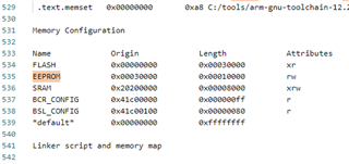
I am attempting to configure or map an area of flash that can be used similar to EEPROM storage in the MSPM0L2228.

Kind regards,

Chris

  • Hi Chris,

    I would open an empty_MSPM0L2228 example and add in the eeprom files that way you have the correct device linker and header files. The application code is MSPM0 agnostic and will work on any MSPM0 device.

    If you want to make use of the dual-bank properties that Cash had mentioned in the linked post, then you can make some adjustments to the linker file (.cmd) and adjust your memory organization.

    Please note that the code example is an example, and not a full program.

    Regards,
    Luke

  • Hi Luke,

    Thank-you, that is a very similar approach to what I am currently looking into, and great to know it is device agnostic.

    Can I ask and double check, does build I am using need to run from RAM?

    I assume it does, but have not seen any configuration options in the examples.

    I have found some descriptions online that suggest there is a config option, but could be for different devices.

    Kind regards,


    Chris

  • Hi Chris,

    The functions inside the example do use the "FromRAM" to update the flash because the original device was a single bank device. Since the L2228 is a dual-bank device you can actually use the normal flash functions.

    There's a system flow to think about in the process though. You can only preform one function in the flash at a time - execute, erase, program. So while you're erasing one bank, all the executable functions need to be performed in the other bank. There's a couple different methods to go about this, but what I would do is keep a subset of functions in my main bank to execute while the other bank is erasing; essentially switch to a state machine.

    You can partition the memory in your .cmd file, to easily section your banks and use the compiler attributes to place functions in the regions of flash.

    Regards,
    Luke

  • Hi Luke,

    Thank-you, so using the normal flash functions, I should be able to execute from bank 0 and use bank 1 as an emulated EEPROM?

    Regarding the .cmd file, I don't seem to have that in my project and assume it is using a default.

    Can you share an example or a link to a reference please?

    Kind regards,

    Chris

  • Hi Team,

    It is very difficult to progress this without seeing something working.

    All the examples are failing, and I have no point of reference for generating a cmd file to move functions in memory.

    Is there an example project that will work without alteration for the L2228 please?

    Kind regards,

    Chris

  • Hi Chris,

    The default .cmd files show how to put functions in specific sections of memory. Looking at my image, you see the .TI.ramfunc is loaded in flash and run from SRAM. The functions themselves then have the tag for the attribute for the section to be placed in that section with those properties.

    You would do something similar for L2228 but break it up into the separate flash banks.

    We don't have a specific L2228 example.


    What are the issues you're getting when you state the examples are failing?

  • Thank-you, I am seeing all the examples end in the Default_Handler, and the last thing that is attempted is a call to DL_FlashCTL_executeCommandFromRAM.

    It originally looked like it was not running from RAM, but the PC is clearly a RAM address:

    The second breakpoint in the screenshot is never reached, the Default_Handler is reached first.

    So the issue is more likely something else with my configuration.

    Ultimately I am wanting to achieve an area of flash on the L2228 that can be used as an EEPROM.

    I have not separated an area in flash and was just wanting to see an example work initially.

    After confirming the function DL_FlashCTL_executeCommandFromRAM is running from RAM, I will configure an area of flash that through the linker that the demo flashctl_multiple_size_write can use. If there is still an error the Default_Handler must be being invoked due to another reason.

  • I have tried with a linker command file and still the code exceptions whilst attempting to erase a sector.

    This has all been performed on our own board, and will be in a position to try similar on the launchpad board tomorrow or early next week.

    The changes I made were as follows:

    and I confirmed that linker file had been used in the successful build by examining the map file:

    Other than seeing how this performs on a launchpad board, I am not sure what else to try, as the root cause for the exception is not obvious.

    It feels like an access problem, but not sure what that could be.

  • Hi TI Team,

    I have found the root cause of the issue I was having with all examples for flash programming on the MSPM0L2228 ending up in the Default_Handler.

    The issue was the startup code in the SDK missing.

    This is what was in the source for the MSPM0L2228 from the SDK mspm0_sdk_2_02_00_05:

    It should have been:

    This was obvious when comparing the running code of the MSPM0G3507, and had been missed when analysing the differences statically.

    Is an update to the SDK planned to avoid similar issues?

  • Hi Chris,

    I was unaware of the change to the startup file, so thanks for bringing this up. I'll get this pushed to our team on what we can do to either add this in by default or provide messaging so it is easily found in the relevant example (a comment in the .cmd file around the .TI.ramFunc section creation could be a suitable place).

    Regards,
    Luke