This thread has been locked.

If you have a related question, please click the "Ask a related question" button in the top right corner. The newly created question will be automatically linked to this question.

TMS570LS3137: HET Capturing Issue

Part Number: TMS570LS3137
Other Parts Discussed in Thread: HALCOGEN,

Tool/software:

Hi, 

Excuse me, I created new topic because the old topic is locked. 

For this issue as a response: e2e.ti.com/.../5663382

Sorry for my late reply. I've been extremely busy.
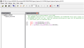
I am currently in the field and measuring frequency. When I use the standard HALCOGen HETProgram, there are 58 instructions as you said in the above topic. I don't need this much, I only need one pwm capture and one edge interrupt. If I do this, can I reduce the LR time by reducing the number of 58 instructions?
Because I have problems with frequency measurement, the sensitivity is not at the level we want. Our measurement range is between 50Khz-110Khz for pwm capture. What do you suggest?

Thank you

  • Hi Ali,

    I don't need this much, I only need one pwm capture and one edge interrupt. If I do this, can I reduce the LR time by reducing the number of 58 instructions?

    You are right, reducing number of instructions will reduce the loop resolution time.

    Along with reducing this loop resolution we can also do the high-resolution capture in N2HET. You can refer below thread, here i attached the code for High Resolution capturing in N2HET:

    (+) TMS570LS0914: How to use N2HET to monitor a variable cycle and variable duty pluse - Arm-based microcontrollers forum - Arm-based microcontrollers - TI E2E support forums

    --
    Thanks & regards,
    Jagadish.

  • Thank you for your support Jagadish 

  • Hi Jagadish, 

    I can't succesfully measured this signal. Thank you for your patience. I tried many times. I have reviewed all the instruction sets but I am writing again because I could not reach the result.

    I will explain step by step what I do:

    1. I imported your project to CCS.

    2. I imported your configured HET program to HET IDE and I reconfigured as below ( I want to capture N2HET1_4 pin pwm):

    3. Then I assembled with Debug->Assemble option. 

    4. I checked that the generated Capture.c file was modified differently from yours.

    5. I configured My board special pin assignment as below: (for signal generating card enable)

    6. Finally I changed cap0 to pin 4 (I don't ensure that is necessary)

    7. I debugged this code:

    As you can see the frequency is inf. 

    Where is my wrong? Can you review my project?

    Thank you :) 

    Best regards

    4061.PWM.zip

  • Hi Ali,

    Apologies for the delay in the response, still no progress on this issue?

    I tested the example code that i shared in my in the linked thread, it worked fine for me.

    --
    Thanks & regards,
    Jagadish.

  • Hi Jagadish,

    I accidentally marked it as solved.

    The problem still there, Can you check my configuration? 

    Where is the problem?

    Thank you

    Best regards 

    Ali.

  • Hi Ali,

    Your configurations and code seem to be fine for me, 

    I want to know where exactly you are applying your input signal? Can you give the pin number that you are applying your capture signal?

    --
    Thanks & regards,
    Jagadish.

  • Hi Jagadish,

    We have a Frequency capturing system. The system's have a signal capturing pin as Het_1 [04]. 

    I was tested this pins can capture correctly with halcogen original code(Not het ide). For me it means the hardware is working fine.

    But it not work with het ide's codes.

    Thanks for all,

    Best regards.

    Ali

  • Hi Ali,

    I tested your code today!

    The only thing i modified in your code is that i changed pwm capturing pin to the HET1[6] like as shown below:

    Because on my board only HET1[6] is easily available and HET1[4] is not terminated, so i used 6 and 7 instead of 4 and 5.

    After doing this modification i used another board for PWM generation of signal with 50us period and 50% duty cycle. And i connected this PWM signal from another board with my TMS570LS3137 board HET1[6] pin, i also made sure to connect ground between these two boards.

    After doing this method you can see the result of my testing's:

    I got exact 50us period with 49.95 duty cycle.

    I am attaching again my modified code here for your reference:

    7217.PWM_Signal_Capture.zip

    I am just suspecting that you might missing connecting common ground between your PWM signal and the board, other than i don't see any other reason for not working.

    --
    Thanks & regards,
    Jagadish.