This thread has been locked.

If you have a related question, please click the "Ask a related question" button in the top right corner. The newly created question will be automatically linked to this question.

MCU-PLUS-SDK-AM243X: Using DP83826 for EtherCat Phy

Part Number: MCU-PLUS-SDK-AM243X
Other Parts Discussed in Thread: DP83869, DP83826E, SYSCONFIG

Tool/software:

Hi Ti Expert,

    We are using our own designed board with EtherCat, and the Phy are DP83826 with its strapping configuration, connected to ICSSG0. 

    Now my problem is that How would I modify the Syscfg file from EtherCAT SubDevice Beckhoff SSC Demo to fit for our own board.

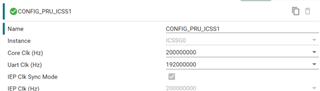
    Firstly, I modified ICSS Instance from ICSSG1 to ICSSG0

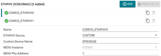
    Then, I went to ETHEPHY Configuration->ETHEPHY Device. DP83869 is the default. Should I keep here DP83869 or I should select None/Custom?

    If I choose Custom, what is the next step?

    As the following link mentioned, you have already done this test. 

https://e2e.ti.com/support/microcontrollers/arm-based-microcontrollers-group/arm-based-microcontrollers/f/arm-based-microcontrollers-forum/1379679/mcu-plus-sdk-am243x-using-dp83849-for-ethercat-on-am243x

   Could you please share the detailed instruction to me?

   My SDK: ind_comms_sdk_am243x_09_02_00_24 ;  CCS: 20.0.1.4__1.6.1

Thanks,

Chunyang


  • Hi Chunyang,

    We already have an example demonstrating the EtherCAT implementation on ICSSG0 instance which uses DP83826E PHY: EtherCAT SubDevice Beckhoff SSC Demo - ICSSG0. If you refer to the example which utilizes R5F1-0 Core within the SDK ({SDK_DIRECTORY}\examples\industrial_comms\ethercat_slave_beckhoff_ssc_demo\am243x-evm\r5fss1-0_freertos), you can get the sysconfig configuration for the same:

    Do note EVMs supported by TI (AM64X-EVM, AM243X-EVM), it is not possible use ICSSG0, as the PRG0_MII1 and PRG0_MII0 pins are not connected to Ethernet PHYs on those EVMs. Would need a dedicated custom board to use this PRU_ICSSG0 instance of ICSSG peripheral.

        If I choose Custom, what is the next step?
    • You can refer to the code under ICSSG0_INSTANCE macro in tiescsoc.c file for the extra configurations done to enable the additional PHYs. In this demo, we use a dedicated HW which has DP83826E PHYs connected to it.

    Do let me know if you need additional support for the same.

    Regards,
    Aaron

  • Thanks Thomas,

    This seems perfectly solved my problem, then I can go ahead my board test.

    BR,

    Chunyang 

  • Hi Aaron,

        Now, I have got my own-designed board which use DP83826 and ICSSG0 for EtherCAT.

        The following is what I am doing to make my board's EtherCAT work. 


        1 Basing on Demo:  ind_comms_sdk_am243x_11_00_00_08\examples\industrial_comms\ethercat_slave_beckhoff_ssc_demo\am243x-evm\r5fss0-0_freertos, I created my own project. 

        2 I copied the example.syscfg from \...\r5fss1-0_freertos to my project. And I modified it's LED and GPIO according to my board.

        3 Modify tiescsoc.c-> tiesc_addOnBoardResetSequence(), according my board to reset Ecat Phy.

        4 I deleted IIC-1 and checked the EEPROM's address, and checked Phy MDIO address.

        5 I built and loaded my code to my board, but my PC showed there is no connection.

        6 I even change the mode of DP83826 from Enhanced to Basic by hardware, there was still no connection with my PC.

        I found that although ICSSG0_INSTANCE is defined, but in ti_drivers_config.h there is only Macros for ICSS1

        /* PRUICSS Instance Macros */
    #define CONFIG_PRU_ICSS1 (0U)
    #define CONFIG_PRU_ICSS1_CORE_CLK_FREQ_HZ (200000000U)
    #define CONFIG_PRU_ICSS1_CORE_CLK_PERIOD_NSEC (5)
    #define CONFIG_PRU_ICSS1_IEP_CLK_FREQ_HZ (200000000U)
    #define CONFIG_PRU_ICSS1_IEP_CLK_PERIOD_NSEC (5)
    #define CONFIG_PRU_ICSS1_UART_CLK_FREQ_HZ (192000000U)
    #define CONFIG_PRU_ICSS1_UART_CLK_PERIOD_NSEC (5.208333333333333)
    #define CONFIG_PRUICSS_NUM_INSTANCES (1U)

        and in tiescsoc.c, it use a lot of pruIcss1Handle but no pruIcss0Handle, for the parameter. like the following: 

    void tiesc_socEvmInit()
    {
    #ifdef ICSSG0_INSTANCE
    tiesc_addOnBoardResetSequence();
    #endif
    const PRUICSS_HwAttrs *pruicssHwAttrs;
    uint32_t inEventLatch0, inEventLatch1, outEventLatch0, outEventLatch1;

    pruIcss1Handle = PRUICSS_open(CONFIG_PRU_ICSS1);
    pruicssHwAttrs = PRUICSS_getAttrs(CONFIG_PRU_ICSS1);

    /* Selecting MII-RT mode in GPCFG mux */
    PRUICSS_setGpMuxSelect(pruIcss1Handle, PRUICSS_PRU0, PRUICSS_GP_MUX_SEL_MODE_MII);
    PRUICSS_setGpMuxSelect(pruIcss1Handle, PRUICSS_PRU1, PRUICSS_GP_MUX_SEL_MODE_MII);

    I am intending to modify all those PruIcss1 to PruIcss0 manually, Am I on the right way?

    Expecting your guidance,

    BR,

    Chunyang 

  • Hi Chunyang,

    I am intending to modify all those PruIcss1 to PruIcss0 manually, Am I on the right way?
    • This is not needed as PruIcss1 is just a naming convention. As you can see, PruIcss1 uses CONFIG_PRU_ICSS1 from sysconfig, which uses ICSSG0 instance:
    • So even though it says PruIcss1, internally it is using ISCCG0 instance. Sorry for the confusion. I'll track to fix this internally within the templates to avoid such confusions going forward.

    Make sure that while using ICSSG0 instance with DP83826 PHY, the following are taken care:

    1. The link polarity is taken care when Enhanced Link is enabled. You can also disable Enhanced Link and see if you're able to scan for the device (which will point out whether the issue is with Enhanced Link configuration)
    2. tiesc_addOnBoardResetSequence() logic is implemented - which you already have taken care of.
    3. tiesc_ethphyInit() logic has been modified to use DP83826 PHY and corresponding mods, instead of DP83869 PHY.
    4. There is a strapping issue in our ICSSG0 add-on board for which a software workaround is implemented in tiesc_ethphyEnablePowerDown() API. You can remove this if this issue is not applicable in your case.
    5 I built and loaded my code to my board, but my PC showed there is no connection.
    • Couple of things to check here is:
      • Are you able to access the PHY registers through MDIO?
      • Are you getting a link change status in the MDIO link register, that is, 0x30010E40 (base addresses for MDIO emulated space) if you're using MDIO firmware workaround (MDIO_MANUAL_MODE_ENABLED) or 0x3003240C if you're not using MDIO emulation
      • Is the firmware receiving EtherCAT frames? This can be confirmed by monitoring 0x30010E00 to 0x30010E03 Vendor Specific ESC Registers:
      • You can also refer to the EtherCAT Debug guide if the issue is similar to frequently reported issue: EtherCAT Debug Guide

    Regards,
    Aaron

  • On an additional note, I recommend you to create a separate E2E thread with reference to this thread as the current thread is marked as resolved and will be difficult to track within internally.

    Regards,
    Aaron