This thread has been locked.

If you have a related question, please click the "Ask a related question" button in the top right corner. The newly created question will be automatically linked to this question.

AM2432: SBL OSPI frequency at high temperature error

Part Number: AM2432
Other Parts Discussed in Thread: SYSCONFIG

Tool/software:

Hi,

I am using AM2432 with the Industrial SDK 11.00.00.08.

We are doing some high temperature tests (around 90 degrees) with our custom sbl_ospi project on a custom board to see how our device behaves. 

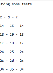
These are our results:

133 + NO PHY     + NO DMA        WORKS
133 + PHY            + DMA              WORKS
166 + NO PHY      + NO DMA      CRASH (first case)
166 + NO PHY      + DMA            CRASH (first case)
166 + PHY            + DMA            CRASH (second case)

We noticed two types of crashes.

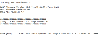
In the first case of crash it seems that the sbl ospi fails to authenticate the image, in particular it fails in: Bootloader_parseMultiCoreAppImage -> Bootloader_verifyMulticoreImage -> Bootloader_socAuthImage -> Sciclient_procBootAuthAndStart, where the check if((retVal != SystemP_SUCCESS) ||  ((respParam.flags & TISCI_MSG_FLAG_ACK) != TISCI_MSG_FLAG_ACK)) is true because of the respParam.flags part (while retVal == SystemP_SUCCESS).


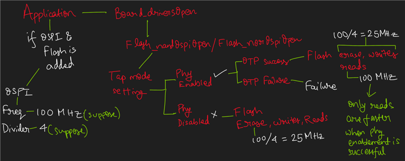
In the second case of crash instead the error seems more at the configuration level because sbl_ospi tries to enable PHY but fails:

The problems described happen at high temperatures, while at normal temperatures problems have never occurred.

We noticed that tests using 133 MHz frequency all seem to pass.

A strange behavior is that if the device is warmed up to high temperature but from off, then when turned on it sometimes does not give problems. The problems are there more often when the high-temperature module is left on for a while (about 1-2 minutes), then turned off and then turned on again. So it seems that somehow the module is sensitive to how long it has been on previously at the time of reboot.

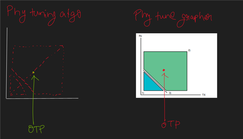
What can we do to better understand and solve the problem? Is this a problem already encountered? Does it have anything to do with the need for OSPI PHY tuning?

Thank you,

Kind Regards,

Andrea

  • Hi,

    I add some details.
    We also performed some tests at higher frequency with 200 MHz, but in this case the tests all passed without any problems, both with and without DMA and PHY.

    It seems that the factor that modifies the success of the tests is just the frequency, but why at 130MHz and 200MHz it works while it is only at 166MHz that gives the problem? I expected that if 166 MHz fails, 200 MHz should fail too.

    Thank you,

    Kind Regards,

    Andrea

  • Hi,

    I add some details for the tests with 166 MHz with no PHY.

    I added the following code to understand how OSPI reads and writes fail.

            DebugP_log("\r\n\r\nDoing some tests...\r\n\r\n");
            Flash_Handle flashHandle = gFlashHandle[CONFIG_FLASH0];
            uint32_t startOffset = 0x380000;
            uint32_t blk;
            uint32_t page;
            uint32_t ret;
    
            Flash_Attrs *flashAttrs = Flash_getAttrs(CONFIG_FLASH0);
    
            uint32_t eraseOffset = startOffset;
            Flash_offsetToBlkPage(flashHandle, eraseOffset, &blk, &page);
            ret = Flash_eraseBlk(flashHandle, blk);
            DebugP_assert(ret == SystemP_SUCCESS);
    
            uint8_t BufferData[256];
            for (int i = 0; i < 256; i++) {
                BufferData[i] = i;
            }
            ret = Flash_write(flashHandle, startOffset, (uint8_t *)BufferData, 256);
            DebugP_assert(ret == SystemP_SUCCESS);
    
            uint8_t dataRx[256] = {0};
            ret = Flash_read(flashHandle, startOffset, dataRx, 256);
            DebugP_assert(ret == SystemP_SUCCESS);
    
            for (int i = 0; i < 256; i++)
            {
                if (BufferData[i] != dataRx[i])
                {
                    DebugP_log("\r\n%x - %x - %x\r\n", BufferData[i], dataRx[i], i);
                    ret = SystemP_FAILURE;
                }
            }
            DebugP_assert(ret == SystemP_SUCCESS);
            DebugP_log("\r\n\r\nTest done, OK!\r\n\r\n");


    This is the result when the test fails:

    Write- reread compare - buffer position (with buffer position = write)

    It seems that sometimes in buffer positions multiple of 0x4 the reread compare values are 1 bit more than what we expected.

    Thank you, 

    Kind Regards,

    Andrea

  • Hi Andrea,

    Thank you for putting forward a detailed explanation of your issue.

    Let me formulate a response stating the debug steps.

    Regards,

    Vaibhav

  • Hi Vaibhav,

    thank you for your response, are there any updates?

    Thank you,

    Best regards,

    Andrea

  • Hi Andrea,

    Thank you for waiting.

    For all the combinations that you mentioned above, I am assuming you have the S28HS512T Flash part on your custom board or is it the S25HL512T?

    Can you please go ahead and provide me the clock divider values as well for all the combinations you stated.

    .Meanwhile, please also read through the following FAQ to gain knowledge on what OSPI Tuning algorithm is: https://e2e.ti.com/support/processors-group/processors/f/processors-forum/1431856/faq-am62a7-ospi-phy-tuning-algorithm

    Additionally go through the following as well:

    Regards,

    Vaibhav

  • Hi Vaibhav,

    thank you for your response.

    The flash we used on our custom board is the S28HS512T flash. The clock divider used is always 4. 

    Thank you for your links, I will look at it and test it in the meantime.

    Best regards,

    Andrea

  • Hi Andrea,


    Do read through the links and let me know once you are aware of the tuning algorithm.

    166 + NO PHY      + NO DMA      CRASH (first case)
    166 + NO PHY      + DMA            CRASH (first case)
    166 + PHY            + DMA            CRASH (second case)

    We will then work on the NO PHY part first.

    Regards,

    Vaibhav

  • Hi Vaibhav,

    thank you for your response.

    I have read the articles. I have a doubt, should this tuning algorithm be done on every single custom board we use? I would think that tuning is needed for every single part and it is not enough to do it once per project, right?

    Let me know what next steps to take to investigate the NO PHY part.

    Thank you,

    Best regards,

    Andrea

  • Hi Andrea,

    166 + NO PHY      + NO DMA      CRASH (first case)

    Lets start in the following way.

    Please go ahead and fill up the following table according to the specified combination.

    Frequency(in MHz) Clock Divider Phy Enabled DMA Enabled Result
    133 4 yes yes works
    133 4 yes no
    133 4 no yes
    133 4 no no works
    166 8 no no
    166 8 yes no
    166 8 yes yes
    200 4 no no
    200 4 yes no
    200 4 yes yes

    I am also assuming you are going to test out the above combinations with the protocol being 8D-8D-8D.

    Regards,

    Vaibhav

  • Hi,

    It would be really helpful if you try to run this on an application like OSPI FLASH IO and if it will work there, then it will work for others(applications) as well.

    If you find it comfortable doing it for SBL OSPI that also works.

    Regards,

    Vaibhav

  • Hi Vaibhav, 

    thank you for your response.

    We are going to do the tests this week and we will share the results with you. In the meantime I have some questions with the OSPI Tuning Algorithm, does this tuning algorithm need to be run on every single custom board we use? I think tuning is necessary for each individual component and it is not enough to run it once per project, right? What happens if we don't use it? Will it just run slower or will the reads/writes be wrong? Should the algorithm be done in the high temperature conditions where the error occurs? And then is it valid for every condition? Should it be done everytime at startup or only once? I read that I need to write a pattern with --operation=flash-phy-tuning-data, but this option is in a cfg file that I should use in UART mode, but with our custom board we can't go in UART mode, is there any other way?

    Thank you,

    Best Regards,

    Andrea

  • Hi,

    We are going to do the tests this week and we will share the results with you.

    Thank you. Looking forward to it.

    In the meantime I have some questions with the OSPI Tuning Algorithm, does this tuning algorithm need to be run on every single custom board we use?

    Yes.

    I think tuning is necessary for each individual component and it is not enough to run it once per project, right?

    Tuning is okay to run once per project as the values of the tuning, what we call as OTP, is saved once you run it and can be used in the subsequent projects as well of the same board given PVT is same.

    What happens if we don't use it?

    Assume one project, computes OTP at a certain PVT and the other project used the same OTP at a different PVT, that would be not an ideal situation to be in.

    What happens if we don't use it? Will it just run slower or will the reads/writes be wrong? Should the algorithm be done in the high temperature conditions where the error occurs? And then is it valid for every condition? Should it be done everytime at startup or only once?

    Let me explain this with the help of diagram in a separate response.

    Should the algorithm be done in the high temperature conditions where the error occurs? And then is it valid for every condition? Should it be done everytime at startup or only once? I read that I need to write a pattern with --operation=flash-phy-tuning-data, but this option is in a cfg file that I should use in UART mode, but with our custom board we can't go in UART mode, is there any other way?

    Phy enabling can be done at any temperature, by looking at the flow diagram you will understand what phy enabling does/has benefits of it.

    For the pattern writing, it has to be just written once, to the flash and the next time it will not be required to write to the flash, as across SDK we do not erase the block where the phy tuning vector is written.

    You can use any external tool to write to the flash once, else I can suggest some changes for the flash part you are using in the drivers itself, which will make sure to write this pattern irrespective of you defining in the .cfg file. 

    I see you are using the S28HS512T flash part, can you tell me if you are planning to operate the flash in hybrid or uniform mode? Please refer this to understand about hybrid vs sector mode: https://e2e.ti.com/support/processors-group/processors/f/processors-forum/1492859/faq-processor-sdk-am62x-4kb-sector-erase-fails

    Regards,

    Vaibhav

  • FYI, here is the flow diagram which will help you understand in an easier way.

  • Hi Vaibhav,

    thank you for your detailed response.

    I reread everything and now I think I understand it well. Correct me if I am wrong:

    • PHY Tuning is done automatically at every startup (when PHY Mode is enabled in sysconfig). Inside SDK code there is the function Flash_norOspiOpen, which takes care of checking if the Attack Vector is present in the last part of the Flash Memory (and in bad case write it, and it is valid until the user does an erase of that part), performs the calculation of the optimal values with the function OSPI_phyTuneDDR and saves them. However, it seems to me that it saves them in a local variable and not in Flash Memory, so it means that this algorithm will have to be done at every startup (I am not sure on this part);
    • After the PHY Tuning, each time a read will be performed the PHY Mode will be used with these parameters. The PHY Mode allows to use the full frequency (so for example with 166MHz and divider 8, it will use 166 MHz against the 166MHz/8 that it would use with this option disabled). However, it can be used only for read operations, while write and erase operations will still go at the frequency with divider in any case;
    • The Attack Vector is written automatically by the Flash_norOspiOpen function, so if I execute my project that already calls this function, there is no need to use the .cfg file in UART Mode;
    • It is also possible to compute this data explicitly with the OSPI_phyTuneGrapher function (as I see here), I can try to run this and compare the values and I expect to find similar values;
    • These OTP values are then valid for the specific device with the specific frequency and at a specific temperature, if one of these factors changes it is better to redo PHY Tuning. So this means that if my device starts at 30 degrees, does the PHY Tuning and then it reaches 90 degrees, another PHY Tuning should be done (I am not sure on this part);

    It seems to me that my problem is more about frequency than PHY Mode, because the 166 MHz frequency seems to fail with or without PHY mode and DMA, while the 200 MHz and 133 MHz frequencies always work.

    I see you are using the S28HS512T flash part, can you tell me if you are planning to operate the flash in hybrid or uniform mode? Please refer this to understand about hybrid vs sector mode: https://e2e.ti.com/support/processors-group/processors/f/processors-forum/1492859/faq-processor-sdk-am62x-4kb-sector-erase-fails

    I read the post and I think we are using Uniform mode, because we never set Hybrid mode as you do in your post.

    Thank you,

    Best Regards,

    Andrea

  • Hi Andrea,

    Thanks for waiting. I am going to address those parts which are incorrect, if I do not address a specific part of your question, then that is a correct understanding.

    However, it seems to me that it saves them in a local variable and not in Flash Memory, so it means that this algorithm will have to be done at every startup (I am not sure on this part);

    The OTP values is indeed saved to a local variable but also to the registers. 
    Please refer this API: OSPI_phySetRdDelayTxRxDLL

    After OTP is computed, the above API is called and it stores the OTP value in the registers. This flow can be found in OSPI_phyTuneDDR function itself.

    Hope this clarifies your doubt.

    However, it can be used only for read operations, while write and erase operations will still go at the frequency with divider in any case;

    When Phy enabling is a success, Read happens at 166

    When Phy enabling is not a success or Phy mode is disabled, Read happens at 166/8

    In either of the cases, writes and erase will happen at 166/8.

    The Attack Vector is written automatically by the Flash_norOspiOpen function, so if I execute my project that already calls this function, there is no need to use the .cfg file in UART Mode;

    For this, I would firstly want to be pin point sure that you are operating the flash in Uniform/Hybrid.

    So, can you tell me if in the SysConfig of your application > FLASH Section do you see some value assigned to the Quirks Function?

    It is also possible to compute this data explicitly with the OSPI_phyTuneGrapher function (as I see here), I can try to run this and compare the values and I expect to find similar values;

    Please understand this with the help of the following illustration:

    The algorithm looks at the minimal number of points to come to a conclusion about what could be the OTP point.

    The grapher on the other hand, plots the entire graph, hence, this can be used to pick the OTP as well. The issue here is that, it takes a lot of time compared to the Phy tuning algo. As here we sweep across every combination: (4 * 128 * 128).

    NOTE: The graph on the left hand side is the same as the one on the right, the red dots denote the points traversed to come to a conclusion of finding the OTP.

    the 166 MHz frequency seems to fail with or without PHY mode and DMA, while the 200 MHz and 133 MHz frequencies always work.

    Does it fail for divider values 4 and 8 ? If yes, then does it fails to read manufacture and device id(check API Flash_norOspiReadId()) or does it fails to compute Phy Tuning? 

    Frequency(in MHz) Clock Divider Phy Enabled DMA Enabled Result
    133 4 yes yes works
    133 4 yes no
    133 4 no yes
    133 4 no no works
    166 8 no no
    166 8 yes no
    166 8 yes yes
    200 4 no no
    200 4 yes no
    200 4 yes yes

    Please fill this table for me to proceed further.

    Regards,

    Vaibhav