This thread has been locked.

If you have a related question, please click the "Ask a related question" button in the top right corner. The newly created question will be automatically linked to this question.

LP-AM263P: Configuring More than 4 GPIO Interrupts

Part Number: LP-AM263P
Other Parts Discussed in Thread: SYSCONFIG

Tool/software:

Hello,

I have a couple questions about creating GPIO input interrupts.

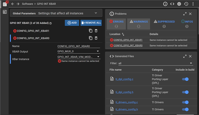
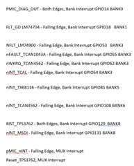
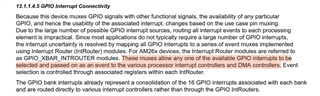
  1. I am trying to trigger input interrupts for 12 GPIOs. 2 of them are MUX interrupts, while the other 10 are distributed across 6 banks. Therefore, I would need 8 interrupt condition instances. Can multiple instances use the same interrupt condition, because I’ve been getting errors what I try to do that.
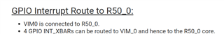
  2. If not, is one core only able to handle four interrupt conditions (for example for core 0 it would be R5FSS0_CORE0_INTR_GPIO_INTRXBAR_OUT_14 to R5FSS0_CORE0_INTR_GPIO_INTRXBAR_OUT_17 which correspond to xbar instances GPIO_INT_XBAR_VIM_MODULE0_0 to GPIO_INT_XBAR_VIM_MODULE0_3)? Or are there other interrupt conditions that I can choose from? And if I do have other interrupt conditions to choose from, what would be their corresponding XBar Instance?
  3. What are the other types of xbar instances used for (such as GPIO_INT_XBAR_ICSS_XBAR_0)

Thank You!

      Saanvi

  • Hi Saanvi,

    Can multiple instances use the same interrupt condition, because I’ve been getting errors what I try to do that.

    Can you please share what exact error you are facing.

    Regards,
    Shaunak

  • If two separate XBARs are set to the same instance, I got the following error (in this case I tried give them both an instance of GPIO_INT_XBAR_VIM_MODULE0_1).

  • Thank you for the information! The links say that only 4 XBars can be routed to VIM_0. However, I have to create 6 bank interrupts + 2 individual interrupts. So I am wondering if it is possible to do more than 4 interrupts. Even in the second link, they ended up doing 1 bank interrupt + 3 individual interrupts. Do you have any examples on how to do more than 4? Here's the breakdown of the interrupts that I need if that helps.

  • Hi Saanvi,

    I've looped in another expert to help here, let's wait to hear their inputs as well

    Regards,
    Shaunak

  • Hey Shaunak,

    just to clarify the issue, Saanvi and I are overall just trying to figure out how to configure sysconfig correctly for all of the interrupts she listed previously.

    1. We are loading this application to core 0
    2. We are using up to 6 banks, so this makes us think we can only use GPIO_INT_XBAR_VIM_MODULE0_0 to GPIO_INT_XBAR_VIM_MODULE0_3. Our impression is that we cannot use GPIO_INT_XBAR_VIM_MODULE1_x to GPIO_INT_XBAR_VIM_MODULE3_x because we are not loading this program to core 1 to 3. Please correct us if our understanding is incorrect.
    3. Since we only have 4 VIM instances we can select for the XBAR instances, we are wondering what other XBAR instances we can choose. What are GPIO_INT_XBAR_ICSS_XBAR, GPIO_INT_XBAR_DMA_TRIG_XBAR, and GPIO_INT_XBAR_SOC_TIMESYNC_XBAR?
    4. An alternative is putting multiple banks on 1 VIM instance. Is this possible? Sysconfig only gives us the ability to choose 1 xbar output per xbar instance.

    Best,

    David Martinez

  • Hi David,

    Our device GPIO expert is OOO on medical leave, From my understanding, since we only ahve 4 VIM Modules (0-3), we won't be able to handle and route 6 interrupts. I'll try to loop in some more XBAR and interrupts experts 

  • Hi David

    We are using up to 6 banks, so this makes us think we can only use GPIO_INT_XBAR_VIM_MODULE0_0 to GPIO_INT_XBAR_VIM_MODULE0_3. Our impression is that we cannot use GPIO_INT_XBAR_VIM_MODULE1_x to GPIO_INT_XBAR_VIM_MODULE3_x because we are not loading this program to core 1 to 3. Please correct us if our understanding is incorrect.

    Your understanding is correct, as can be seen from the TRM.

    An alternative is putting multiple banks on 1 VIM instance. Is this possible? Sysconfig only gives us the ability to choose 1 xbar output per xbar instance.

    No, as can be seen from the TRM again, each output can only be sourced from a single input. Assigning a second gpio source to an already-used VIM is not possible as it would overwrite the first.

    Since we only have 4 VIM instances we can select for the XBAR instances, we are wondering what other XBAR instances we can choose. What are GPIO_INT_XBAR_ICSS_XBAR, GPIO_INT_XBAR_DMA_TRIG_XBAR, and GPIO_INT_XBAR_SOC_TIMESYNC_XBAR?
    1. GPIO_INT_XBAR_ICSS_XBAR: This routes GPIO interrupts to the PRU-ICSS (Programmable Real-time Unit Industrial Communication Subsystem).
    2. GPIO_INT_XBAR_DMA_TRIG_XBAR: This routes GPIO interrupts to trigger EDMA (Enhanced Direct Memory Access) channels. This is useful for starting memory transfers based on a hardware event without CPU intervention. 
    3. GPIO_INT_XBAR_SOC_TIMESYNC_XBAR: This is for the SoC-level Time Synchronization module. It's typically used for applications needing precise time-stamping of GPIO events

    From the TRM, we can also see that the intended architecture for handling a large number of GPIO interrupts is to offload them to the Programmable Real-time Unit (PRU)

    The design of the GPIO Interrupt Router (the main crossbar) allocates a vastly larger number of interrupt outputs to the PRU-ICSS than to the main R5F cores.

    • R5FSS0-CORE0 VIM Inputs: As we established, outputs 14, 15, 16, and 17 of the GPIO XBAR are routed to the VIM for Core 0. That is a total of 4 direct inputs.
    • PRU-ICSS INTC Inputs: As shown in Table 15-156 of the interrupts TRM ("GPIO Interrupt Router Output Destination Summary"), outputs 30 through 61 are routed to the PRU-ICSS interrupt controllers. This is a total of 32 dedicated inputs for the PRU subsystem.

    The approach to do this should be something like the following (We'll loop in the PRU expert to confirm this):

    • Route 4 Critical Interrupts Directly
    • Route the remaining interrupts to PRU using GPIO_INT_XBAR_ICSS_XBAR
    • Program the PRU to get the event from GPIO, and then trigger a new event back to the R5F VIM, PRU has 16 dedicated event outputs for this purpose 
    • Create One R5F ISR for the PRU

    To get started on this you can look at the PRU-IO example provided in the SDK.

    Best Regards,
    Akshit

  • Hi Akshit,

    Thank you for the response. I have a couple more questions about how to implement this.

    1. 

    In this code for creating a bank interrupt using a VIM Module, is there a way to determine which of the pins caused the bank interrupt?

    2. In the same above screenshot, why does gGpioBaseAddr not change depending on what bank we are trying to create the interrupt for? And how do I choose the correct gGpioBaseAddr?

    3.

    You said in the previous message to reference the PRU-IO example. Is the code I should be referencing? If so, I still don't really understand how to trigger a new event back to the R5F VIM? And how do I create a R5F ISR for the PRU, and how do I initialize the pins that I want to create interrupts for to the PRU?

  • Hello, I wanted to follow up on this thread!

  • Hi Saanvi,

    Our expert is OOO, please expect a response by mid next week.