This thread has been locked.

If you have a related question, please click the "Ask a related question" button in the top right corner. The newly created question will be automatically linked to this question.

AM2434: EtherCAT Multi-Node Connection Issue with AM2434 and DP83822

Part Number: AM2434

Tool/software:

Hi all,

We are currently using AM2434 ALV MCU with DP83822 PHY for EtherCAT Communication. We have encountered some issues.

Environment Configuration:

  • Chip: AM2434
  • PHY: DP83822
  • SDK Version: mcu_plus_sdk_am243x_08_06_00_45
  • EtherCAT Firmware Version: g_v1.3 (path: \mcu_plus_sdk_am243x_08_06_00_45\source\industrial_comms\ethercat_slave\icss_fwhal\firmware\g_v1.3)

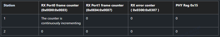
Testing method: The Master is connected to two Slave stations to perform power on/off testing.

  • topology: Master Station 1 ( AM2434 with DP83822 )  Station 2 ( AM2434 with DP83822 )

  • Power On/Off Test Description: After the Master successfully connects with Station 1 and Station 2, all three devices are powered off simultaneously. Then, they are powered on simultaneously again, and the connection is checked to confirm if it is restored properly. This cycle is repeated continuously to verify the stability of the power on/off process.

Issue Description: During the test cycles, after powering on, the Master occasionally fails to establish a connection with Station 2. At the time of the issue, the Master successfully connects with Station 1 but cannot connect with Station 2. Observing Station 2 shows that the LINK status is not established.

Slave Initialization Process:

  • Our initialization process is based on the example code settings (path: \mcu_plus_sdk_am243x_08_06_00_45\examples\industrial_comms\ethercat_slave_beckhoff_ssc_demo\am243x-evm).
  • The only difference is that we use the DP83822 PHY, so the configuration in tiesc_ethphyInit is slightly different. Below is the description of the configuration process adopted for the DP83822:
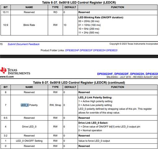
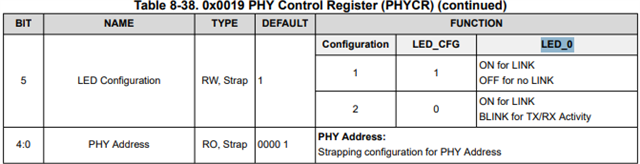
    1. Set PHYCR to 0x0019: Enable bits 5 and 15
    2. Set ANAR to 0x0004: Enable bits 0, 6, 7, and 8
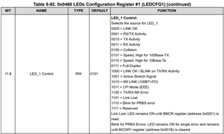
    3. Set IOCTRL1 to 0x0462: Configure LED_1 GPIO Configuration as 001 LED_1 (Default: Speed, High for 100Base-TX)
    4. Set LEDCFG1 to 0x0460: Configure LED_1 Control as 0001 RX/TX Activity
    5. Enable the MDIO Link change interrupt (MDIO_LINKSEL_MLINK_MODE)
    6. Set RCSR to 0x0017: Select MII mode
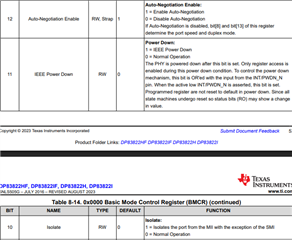
    7. Set BMCR to 0x0000: Enable bit 12
    8. Set BMCR to 0x0000: Enable bit 9

Preliminary Investigation:

  • During the occurrence of the issue, we performed the following tests:
    • Restarting only Station 1, the PHY A connection of Station 1 recovered normally.
    • Restarting only Station 2, the PHY A LINK status of Station 1 remained erroneous.
  • We then changed the connection order of the two stations to Master → Station 2 → Station 1, and performed the power on/off cycle test. After this, the abnormal condition changed to an intermittent failure to establish a connection with Station 2, with Station 2’s PHY A LINK status not established. Even when replacing with different Slave devices (such as AM2434 + DP83822), as long as the Master is connected to multiple stations, the problem always occurs at the first station, with PHYA LINK not established. Therefore, we suspect this issue is unrelated to the hardware itself.
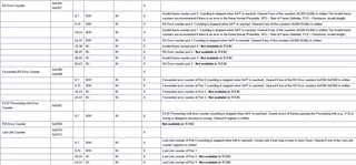
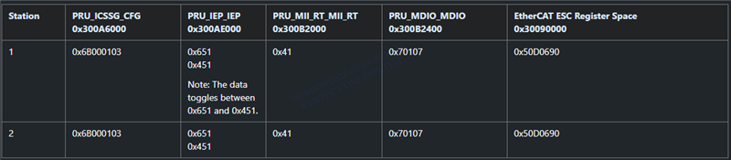
  • During the occurrence, we read the PHY registers at run time and found abnormal settings in Station 1’s PHY A, with the following values:
    During the issue, PHY registers were read at run time
    Station1 Station2
    PHY REG PHYB PHYA
    PHYIDR2 0x0003 41536 41536
    PHYCR 0x0019 35875 32802
    ANAR 0x0004 449 449
    IOCTRL1 0x0462 8192 8192
    LEDCFG1 0x0460 12544 7168
    APDC 0x041F 0 0
    RCSR 0x0017 73 65
    BMCR 0x0000 12544 7168
    BMSR 0x0001 30829 30793
    內容 PHYB PHYA
    PHYIDR2 0x0003 41536 41536
    PHYCR 0x0019 32803 35874
    ANAR 0x0004 449 449
    IOCTRL1 0x0462 8192 8192
    LEDCFG1 0x0460 12544 12544
    APDC 0x041F 0 0
    RCSR 0x0017 65 65
    BMCR 0x0000 12544 12544
    BMSR 0x0001 30793 30829

    During normal communication, PHY registers were read at run time
    Station1
    PHY REG PHYB PHYA
    PHYIDR2 0x0003 41536 41536
    PHYCR 0x0019

    35875

    35874
    ANAR 0x0004 449 449
    IOCTRL1 0x0462 8192 8192
    LEDCFG1 0x0460 12544 12544
    APDC 0x041F 0 0
    RCSR 0x0017 65 65
    BMCR 0x0000 12544 12544
    BMSR 0x0001 30829 30829
  • After completing the tiesc_ethphyInit configuration, we read back the PHY registers to verify the settings were correct. However, we still occasionally encounter abnormal behavior with Station 1’s PHY A.
  • We observed that the abnormal PHY register values usually occur when the ESC AL Status (0x0130) is in the Init State—that is, before EtherCAT enters the OP State. The issue appears prematurely.

Regarding the EtherCAT power on/off test with multiple stations connected to the AM2434, we occasionally see abnormal behavior with the DP83822 PHY on Station 1.

Could you please advise what might cause this issue? Are there recommended debugging and troubleshooting steps we could follow?

Best Regards,
Wei

  • Hi Wei,

    Recommend you to go through the TI ESC EtherCAT SubDevice Debug Guide for frequently reported issues related to PHY configuration and link detection.

  • Hi Aaron,

    Regarding the TI ESC EtherCAT SubDevice Debug Guide, we found that it does not effectively help us in troubleshooting or resolving the issue we are facing. This is because our issue is intermittent and does not occur immediately after power-up or during the initial communication establishment.

    We have confirmed that the PHY initialization performed by the software is correct at the moment the issue occurs. However, during runtime when the issue is reproduced, we observed that the values read from the PHY registers — LEDCFG1 (0x0460) and BMCR (0x0000) — do not match the expected settings.

    What could be the possible reasons for this issue?

    BR, Wei

  • Hi Wei,

    Looks like the LED1 is configured to 0x1C00 value during this scenario, that is LED1 Control : TX/RX MII Error:

    Coming to the BMCR Register, it also has value 0x1C00, which implies the following bits are set:

    Looks like the PHy is going to a power down state. Are you re-configuring LED1 somewhere within the application. Additionally, can you monitor the following ESC Registers to check if the Firmware is receiving any RX error frames or link drops:

    Regards,
    Aaron

  • Hi Aaron,

    In the APP, after completing the PHY configuration using tiesc_ethphyInit(), there is no further reconfiguration of the PHY. We have verified that all PHY register settings are correct before executing EtherCAT MainInit().

    The abnormal behavior we observed occurs when the ESC AL Status remains in the Init State.

    At the moment when the issue is reproduced, the following ESC DL Status register values were observed:

    • Station1: ESC DL Status (0x0110) = 22039

    • Station2: ESC DL Status (0x0110) = 21765


    We would like to consult on the following questions:

    1. Are there any other ESC registers we can check to help further identify the root cause when the issue occurs?

    2. Regarding the DP83822 PHY, we would like to clarify:

      • Is it possible for the DP83822 to autonomously change the LEDCFG1 or BMCR register values without software intervention?

      • During EtherCAT operation, is there any chance that EtherCAT itself might alter the state or register values of the DP83822 PHY (e.g., modify its configuration)?

    BR, Wei

  • Hi Wei,

    Station1: ESC DL Status (0x0110) = 22039
    • This corresponds to 0x5617 which implies there's physical link on Port0 and stable communication has been established on the port and Port1 is in closed loop configuration.
    Station2: ESC DL Status (0x0110) = 21765
    • This corresponds to 0x5505 which implies there's no physical link on Port0 and Port1. This is expected in a daisy chain as Port1 of Station1 has no link detected.

    Couple of things you can do to root-cause this behavior:

    1. Can you disable Enhanced Link (bspInitParams->enhancedlink_enable = TIESC_MDIO_RX_LINK_DISABLE) in tiescsoc.c file and see if you still face the issue.
    2. You can monitor 0x0E00 to 0x0E07 Vendor Specific ESC Registers to for port0 and port1 RX frame counter to see if valid frames are received by EtherCAT firmware.
    3. The PHY configuration is done using MDIO_USER_ACCESS_REG of the MDIO module. One thing you can do is add a Hardware Watchpoint at the MDIO_USER_ACCESS_REG offset, that is, 0x30090E40 + 0x80 if you're using MDIO Firmware Workaround (MDIO_MANUAL_MODE_ENABLED) or 0x300B2480 if you're not using the MDIO firmware emulation. With this, we should see who is writing to MDIO_USER_ACCESS_REG during the ongoing EtherCAT communication. To add a HW Watchpoint, you can do the following:
      • Once you have loaded the application on the R5F core, open Breakpoints from View --> Breakpoints
      • Right click on the Breakpoints Window and choose Breakpoint -> Hardware Watchpoint.
      • In the Hardware Watchpoint Box, enter the address in "Location field" and choose Write in the "Memory" field,
      •   
      • After "OK", you can verify in the Breakpoints Window if the required Breakpoint is enabled.
      • You can add this once the initial PHY register configurations are complete. 

    Is it possible for the DP83822 to autonomously change the LEDCFG1 or BMCR register values without software intervention?
    • Under normal operation without hardware/power issues, the LED1 configuration should remain stable as set by software. The registers don't have any auto-update or self-modifying capabilities.

    During EtherCAT operation, is there any chance that EtherCAT itself might alter the state or register values of the DP83822 PHY (e.g., modify its configuration)?
    • This is very unlikely as there are no such re-configuration of PHY registers during EtherCAT operation. Only possibility I can think is if there's any calls to ETHPHY_CMD_SOFT_RESTART elsewhere in the code could affect LED settings.

    Regards,
    Aaron

  • Hi Wei,

    Additionally, can you monitor the following ESC Registers to check if the Firmware is receiving any RX error frames or link drops
    • I would like to stress on this point once again as when RX_ERR threshold is detected, the link partner is informed by restarting the Auto-Negotiation mechanism via the MII Management Interface.
    • You can monitor the ESC register space from 0x0300 to 0x0307 for the RX Error frames detected within the PRU firmware and also from the PHY Register (offset 0x15):

    Regards,
    Aaron

  • Hi Aaron,

    1. Setting bspInitParams->enhancedlink_enable to TIESC_MDIO_RX_LINK_DISABLE results in failure to establish communication with the Master.
    2. After the issue is reproduced, the following statuses are monitored at runtime.

    3. Using a Hardware Watchpoint, we confirmed that no other functions are accessing the PHY registers.

    Could you please help confirm this?

    BR, Wei

  • Okay so 0xE00 aligns to previous finding that only Port0 of Station 1 is identified and port1 of Station 2 remains closed, thereby not detecting any other Stations in the daisy chain.

    Can you also make sure all the required hardware connections mentioned in Hardware Requirements are present in your device.

    Regards,
    Aaron

  • Hi Aaron,

    Both Station1 and Station2 meet all the necessary hardware connections and component requirements as specified in the Hardware Requirements documentation.

    We have also tried swapping the connection order of Station1 and Station2, and observed that the issue follows the connection order. Specifically, when Station2 is placed first in the chain, its Port0 is recognized correctly, but Station1, now at the end, has its Port1 in a closed state.

    Based on this observation, we believe the issue is unlikely to be hardware-related, and may instead be associated with software logic or the initialization process.

    BR, Wei

  • Specifically, when Station2 is placed first in the chain, its Port0 is recognized correctly, but Station1, now at the end, has its Port1 in a closed state.

    Does this mean that Port0 of Station1 (now the end device) is getting detected?

  • Hi Wei,

    Could you also share the ICSS Memory dump? I'm referring mainly to the following spaces:

    Regards,
    Aaron

  • Does this mean that Port0 of Station1 (now the end device) is getting detected?

    Port1 of Station2 is not being detected, and both Port0 and Port1 of Station1 also fail to establish detection.

  • Hi Aaron,
    The following is the result of the ICSSG memory dump.
    Information read at runtime during issue reproduction:

    The ICSSG memory data is the same during normal communication and when the issue is reproduced.

    BR, Wei

  • Hi Wei,

    Port1 of Station2 is not being detected, and both Port0 and Port1 of Station1 also fail to establish detection.
    • Thanks for the clarification.
    Information read at runtime during issue reproduction:
    • Sorry for the miscommunication. What I was referring was to the complete memory space under the following ICSS modules:
      • PRU_ICSSG_CFG Registers (0x300A6000 to 0x300A6194)
      • PRU_MII_RT_MII_RT Registers (0x300B2000 to 0x300B206C)
      • PRU_MDIO_MDIO Registers (0x300B2400 to 0x300B248C)
      • EtherCAT ESC Registers (0x30090000 to 0x30090ED0)

    Regards,
    Aaron

  • Hi Wei,

    We are checking this internally with the corresponding team parallelly.

    Could you also share the schematic of your board, where we want to confirm the pin connections.

    Regards,
    Aaron

  • Hi Aaron,

    I have sent you the ICSSG memory dump and the schematic via email.
    Kindly help review the information at your convenience. Thanks

    BR, Wei

  • Thank you Wei for the files. We do see some mismatch in the connection. We will do a thorough review and get back to you by tomorrow.

    Regards,
    Aaron 

  • Hi Wei,

    On reviewing the ICSS MDIO Registers, I needed to confirm couple of Enhanced Link configurations:

    • The PHY Address of ECAT IN port is 2 and PHY Address of ECAT OUT port is 3. This is aligned in the Syscfg ?
    • I believe the link polarity is configured to ACTIVE_LOW.

    Can you also provide the complete PHY Register dump. Needed to check on couple of LED_0 configurations such as LEDCR (0x0018), PHYCR (0x0019), MLEDCR(0x0025), SOR1(0x0467):


    This is to confirm the LED configurations required for Enhanced Link on Station1.

    Regards,
    Aaron

  • Hi All,

    Please review the terminations on the MDI side as well as the capacitors for the supply rails for EPHY.

    https://e2e.ti.com/support/processors-group/processors/f/processors-forum/1521263/faq-am625-am623-am620-q1-am62ax-am62px-am62d-q1-am62l-am64x-am243x-design-recommendations-custom-board-hardware-design---queries-related-to-rmii-interface-and-rmii-ti-ephy

    I am not sure if this is a cause but wanted to be sure i highlight the same.

    Regards,

    Sreenivasa