This thread has been locked.

If you have a related question, please click the "Ask a related question" button in the top right corner. The newly created question will be automatically linked to this question.

AM2634: bootstrap resistor value in DP83822

Part Number: AM2634
Other Parts Discussed in Thread: SYSCONFIG

Tool/software:

hi TI,

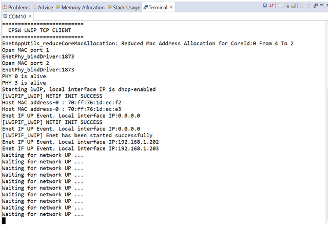
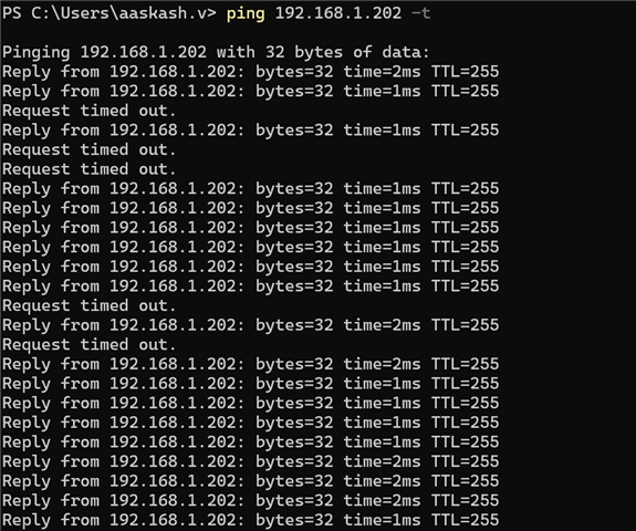
I was working on ethernet in our own customized board for pinging 2 ips we are using the phy DP83822 and i am using version 10.2.00.13 so in that i am using the example code enet_cpsw_rawhttpserver_am263x-cc_r5fss0-0_nortos_ti-arm-clang.

Our bootstrap resistor settings given below:

  Phy-0 Phy-1
  RH RL Rh Rl
Rx_ERR open open open open
         
Rx_DV 2.49 open 2.49 open
         
CRS 13K 1.96K 13K 1.96K
         
COL open 1.96K open open
         
Rx_D3 10K 2.49k 10K 2.49k
         
Rx_D0 open open 2.49 open
         
Led open open open open
         
Rx_D1 open open open open
         
Rx_D2 open open open open

After we checked the reference clock we are getting 3Mhz - 5Mhz 

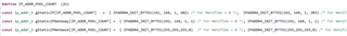
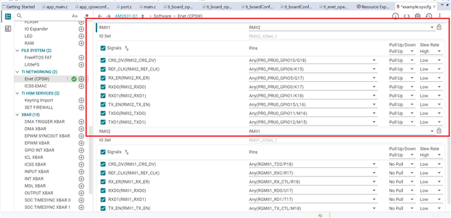
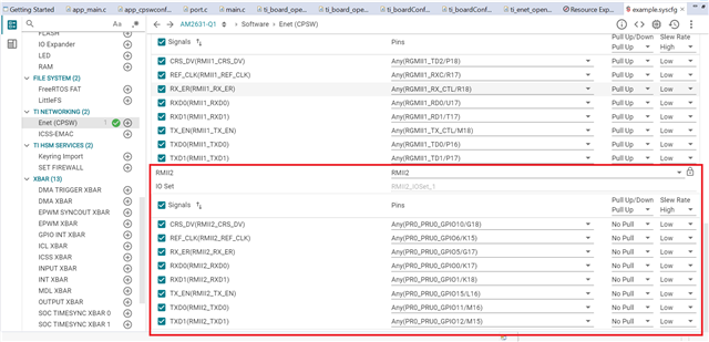
below are the sysconfig configurations:


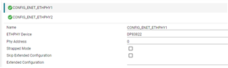
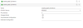
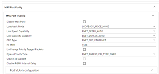
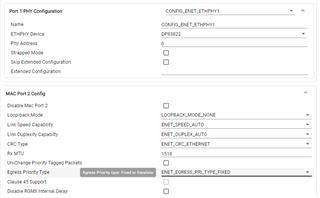
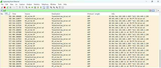
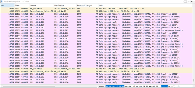
we can't be able to ping ips using this above configuration can you say what i need to do for this and we are using the below config for the bootstrap resistor.

SNLR053 1.xls

1. can you explain what is the resistor value which i need to set for bootstrap resistor for both the phy address 1 and 3.

2. what i need to set in the sysconfig configurations.

your response is mostly welcome 

Thank you,

  • Hi Akash,

    I have asked our PHY team for help here.

    Regards,
    Shaunak

  • Hi Akash,

    The strap table sets:

    PHY0 Address = 0x0
    PHY1 Address = 0x3
    RMII enabled, 50M reference clock (XI) input

    After we checked the reference clock we are getting 3Mhz - 5Mhz 

    Is this the reference clock on XI of PHY? PHY requires 50M input clock on XI with strap table config.
    Please also confirm if registers are accessible.

    Thank you
    Evan

  • Hi Evan,

    can you give answer for below 3 points....

    1. From the XTAL we got 25MHz we can observed and in the reference clock we got only 3Mhz - 5Mhz on ref_clk pin according to the below thread

     AM2634: Bootstrap configuration for DP83822 in RMII mode - Arm-based microcontrollers forum - Arm-based microcontrollers - TI E2E support forums

    and can I follow excel, which u mention in the above thread?

    2. If no please provide the bootstrap resistors configuration for all the resistors...

    3. I did some other configuration on the bootstrap resistors for phy - 2 and if i use the below resistor for the bootstrap resistors we are getting the phy ref clock as 50Mhz.

    Addr for phy 2 i configured as 3

      RH RL
    COL_2 10K 10K
    RX_D0_2 10K 10K
    RX_D1_2 10 k 2.49k
    RX_D2_2 10 k 2.49k
    RX_D3_2 10K 2.49K
    LED_0_2 open open
    LED_1_2 open open
    CRS_2 6.2k 2k
    RMII2.RX_ER_3 open open
    RX_DV_2 5.76k 2.49k

    so in this combination i tried and i could able to ping the IP also we are getting timeout

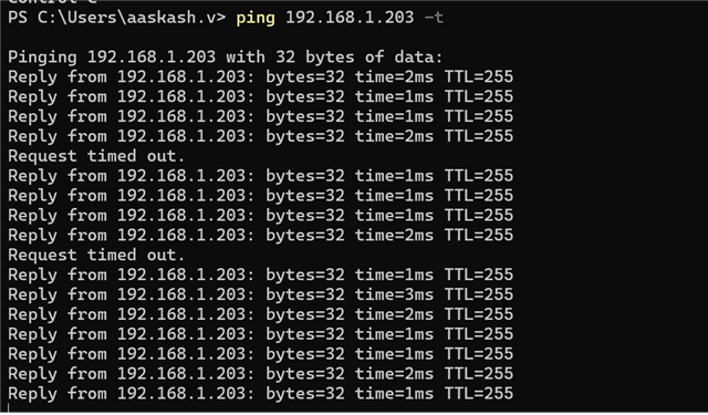
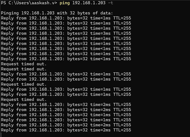
      can u say wat is the issue for this?
  • Hi Akash,

    Here are the bootstrap values for the requirements listed in the other thread:

    Requirements Value Strap Mode PU Value PD Value
    PHY1 Address 0x00 COL 1 OPEN 1.96k
    RX_D0 1 OPEN OPEN
    RX_D1 1 OPEN OPEN
    RX_D2 1 OPEN OPEN
    RX_D3 1 OPEN OPEN
    PHY2 Address 0x11 COL 4 OPEN OPEN
    RX_D0 4 2.49k OPEN
    RX_D1 1 OPEN OPEN
    RX_D2 1 OPEN OPEN
    RX_D3 1 OPEN OPEN
    Mode of Operation 100Base-TX, Full-Duplex, Auto-MDIX RX_D3 1 OPEN OPEN
    RX_D0 1 or 4 OPEN (1) or 2.49k (4) OPEN
    LED_0 4 OPEN OPEN
    LED0 Configuration Blink TX/RX Activity CRS 2 13k 1.96k
    LED1 Configuration ON for 100Mbps speed
    MAC Configuration RMII Master RX_DV 3 5.76k

    2.49k

    One clarification - is PHY intended for RMII master or slave mode? If slave mode, please change RX_DV to mode 4 (2.49k PU // OPEN PD).

    I'm unclear on the resulting strap values for the most recent configuration you have, please follow datasheet recommendation for PU//PD to clarify mode set.

    if i use the below resistor for the bootstrap resistors we are getting the phy ref clock as 50Mhz.

    This is the PHY's output reference clock RX_D3?

    Regarding the timeout issue, this could be a result of some PPM offset at the MAC & PHY's input clock pins. PPM offset could cause buffer underrun/overrun issues, resulting in occasional packet drops. Please share a readout of register 0x17 after ping operation to confirm this.

    You can also increase the RMII buffer elasticity with 0x17[1:0] = '11' to allow greater PPM offset tolerance.

    Thank you,
    Evan

  • Hi Evan,

    Thank you for your support!!!!.... As u mentioned the above resistor we tried in our customized board, we are getting 50Mhz ref-clock

    we imported the example code enet_cpsw_tcpclient rtos project to ping 2ip's in 2 different port and i tested in the eval board it was working with DP83826 ic.

    we are getting the debug log as 2 and 3 alive

    so according to that i configured in sysconfig as phy 2 address as 2 and 3. 

    mac port configuration manually,

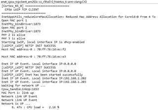
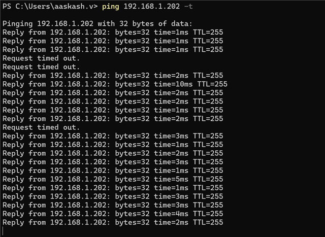
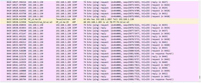
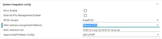
      in auto assign we couldn't able to ping the any ip's 

    the below is the static ip i allocated and i tried to ping

    so, in that case i could be able to ping the ip 192.168.1.202 but not 192.168.1.203.

    can you expalin why the phy 2 and phy 3 is alive can you give justification? or it is ok?

  • Hi Akash,

    I'm not clear if "PHY<x> is alive" corresponds to PHY strapped at <x> address - checking with AM2x team to confirm.

    Assuming MAC is able to identify MDIO bus of both PHYs, then ping failure for 202 subnet is likely sysconfig RMII configuration issue.

    As one of the PHYs is working for ping, I recommend using that as reference to validate RMII config on failing PHY, and confirm PHY address strap / syscfg setting is correct on failing PHY.

    Thank you,
    Evan

  • hi Evan,

    As u mentioned the above for RMII buffer elasticity i tried to configure '11' in this structure

    // 0x0017 is the RCSR register
    // Bits [1:0] = 11 (0x3) => 10-bit elasticity buffer


    pRegAccessApi->EnetPhy_rmwReg(pRegAccessApi->pArgs,
                                                                                         0x0017, // RCSR register
                                                                                         0x0003, // Mask bits [1:0]
                                                                                         0x0003); // Set bits to '11' for 10-bit tolerance

    typedef struct
    {
         int32_t (*EnetPhy_readReg)(void* pArgs, uint32_t reg, uint16_t *val);

         int32_t (*EnetPhy_writeReg)(void* pArgs, uint32_t reg, uint16_t val);

         int32_t (*EnetPhy_rmwReg)(void* pArgs, uint32_t reg, uint16_t mask,
                       uint16_t val);

         int32_t (*EnetPhy_readExtReg)(void* pArgs, uint32_t reg,
                        uint16_t *val);

          int32_t (*EnetPhy_writeExtReg)(void* pArgs, uint32_t reg,
                         uint16_t val);

         /*!Argument that needs to be passed to the above callbacks */
              void* pArgs;

    } Phy_RegAccessCb_t

    i could not able to increase the Receive Elasticity Buffer size so can you give the sample code for this..


  • Hi Akash,

    This function call looks correct to write register 0x17, I'm unclear why it's not taking effect.

    However, as you are able to ping one of the PHYs, I suspect this register config is not required. Instead, we should focus on the syscfg and PHY address configuration between working/failing PHYs. Please let me know if you can identify any differences between working and failing PHY configs, aside from distinct PHY address strap.

    Thank you,
    Evan

  • Hi Evan,

    sorry for late replay, i just use the same resistor value which you suggested in another customized board and at that time we are able to get the phy 0 and phy 3 as alive.  

    and we are using the example code as enet_cpsw_tcpclient.


    so i just configured in sysconfig phy -  0 and 3 and now the ethenet ping happening so here we observed 2 things


    1. if I configure the RMII2 In the 1st instance we can able to ping the 1st IP


    2. if I configure the RMII2 In the 2nd instance we can able to ping the 2nd IP


    can you say why this scenario is happening?

    i am attaching my example.syscfg below for your reference can u say why the time out issues is happening?

     4214.example.syscfg.zip

  • Hi Akash,

    Please share the schematic - I'd like to review RMII connections between AM263 and each PHY.

    I am tagging MCU team to help review syscfg for RMII.

    Thank you,
    Evan

  • Hi Evan,

    I got the issue and resolved the issues due to sysconifg if u configure the pin it is not reflecting on  pinmux.c file so i raised one ticket in forum and i resolved that.so now i could able to ping both the ip's in debugging also in flash.


    so still i am facing the Request time out  issue can u say wat is the issues?

  • Hi AK,

    Glad to know that the other Pinmux RMII issue resolved this issue and you can Ping now. Request time out issue doesn't directly point to issue with AM26x, it can be due to network setup as well.

    In your application, can you open lwip_stats in the expression window (after halting the R5F core) and see if there are any packet drops for ICMP? If ICMP packets are dropped at AM26x side, then you will be able to see that here. You can refer: https://dev.ti.com/tirex/explore/node?node=A__AEIJm0rwIeU.2P1OBWwlaA__AM26X-ACADEMY__t0CaxbG__LATEST to get steps on checking lwip_stats. Also, check CPSW Stats and see if there are any packet drops at MAC Port level (refer the same page for steps).

    If we do not see any packet drops at CPSW or LwIP side, then I think the packet drops are due to some issues outside the scope of AM26x.

    Regards,
    Shaunak

  • Hi Evan,

    As per ur previous discussion i observed that, I am debugging the Code and I am monitoring at the time of request time out i pause my code and i am checking where the issue is happening so I can see every time if I get time out it is halt on this part.

    I observed in expression LWIP_STATS, here i observed packet drop is 0. in ICMP


    But in Etharp it show some drop.


    i am thinking that our server means hardware is sending the data and our driver code is Struk/halt somewhere at the time of Request time out and again after some time it is started sending the packet.

    because every time of debugging I observed that whenever it is request timeout going to happen pause my code and it was halt on TimerP_getCountPriv() this function.   --- this is just my observation.


  • Hi AK,

    In your lwip_stats I do see some ARP protocol error packets. Can you please check the ARP packets being sent to the AM26x (probably through wireshark?)

    An ARP protocol error can indeed cause an ICMP timeout. ICMP (Internet Control Message Protocol) relies on ARP (Address Resolution Protocol) to map IP addresses to MAC addresses within a local network. If ARP fails to resolve an IP address to its corresponding MAC address, the ICMP echo request (like a ping) will fail, resulting in a timeout. 

    Regards,
    Shaunak

  • hi Shaunak,

    1. Here we are connected our ethernet directly pc -> mcu there is no intermediate

    I observed the ARP protocol error packets in the wireshark and i attached below.


    Below i filtered only the ARP protocols.


    can you say what is the solution for this 

    1. I have one question i soldered the bootstrap resistor according to this thread which u mention above so is there any possibility that if we change our resistor our Request time out error will resolve?

  • hi TI teams,

    It's been a while so can u give some suggestion for the above threads. Yoru's comments are mostly helpful for us.

  • Hi AK,

    Our expert is OOO, please expect a response by mid next week.

  • Hi AK,

    can you say what is the solution for this 

    Based on the wireshark screenshots filtered for ARP packets, I do not see any ARP error packets, infact, for every ARP request to locate an IP address, the MCU has responded with the relevant MAC address. Maybe there is some firewall blocking the packets from external world to the PC (you can check this as well to make sure no packets are dropped or there isn't a lot of traffic overload in the link). To avoid PC overheads as well, try to test with a Linux PC once 

    1. I have one question i soldered the bootstrap resistor according to this thread which u mention above so is there any possibility that if we change our resistor our Request time out error will resolve?

    This can also be due to signal integrity or timing issues. For RMII mode, I don't expect straps to make a difference if PHY link is up and able to transmit/receive from MAC & link partner. It could be the cause in RGMII mode with timing delays, but RMII mode has no configuration like this through straps

    Regards,
    Shaunak