This thread has been locked.

If you have a related question, please click the "Ask a related question" button in the top right corner. The newly created question will be automatically linked to this question.

AM2434: Question about OSPI-READ half-level (Continue)

Part Number: AM2434
Other Parts Discussed in Thread: SK-AM64B, SYSCONFIG

Tool/software:

A few months ago, we push a question on the forum regarding the issue of half-level signals when reading flash data via OSPI, as detailed in this link:

e2e.ti.com/.../5739028

The topic has since been automatically closed, but we never received a clear explanation of the root cause or an effective solution to the problem.

We recently conducted further testing using the EVM board and SDK examples. The issue can be reliably reproduced following the steps below. We hope TI's experts can continue analyzing this problem to determine its root cause and explore potential solutions.

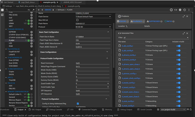
1.  Import the SDK example project: "mcu_plus_sdk_am243x_11_00_00_15\examples\drivers\ospi\ospi_flash_dma\am243x-evm"

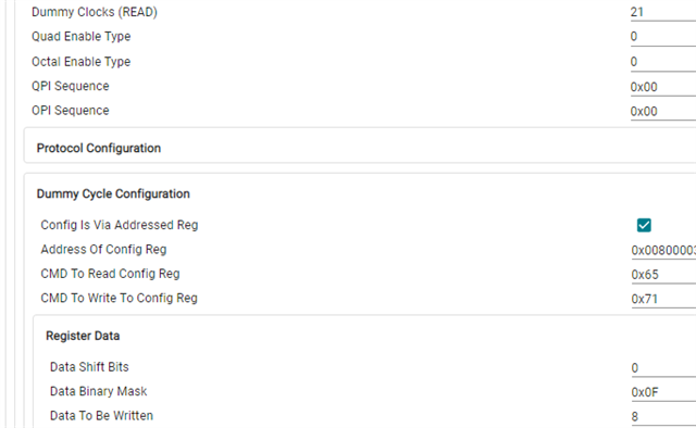
2. Unckeck "Enable PHY Mode" on example.syscfg->OSPI

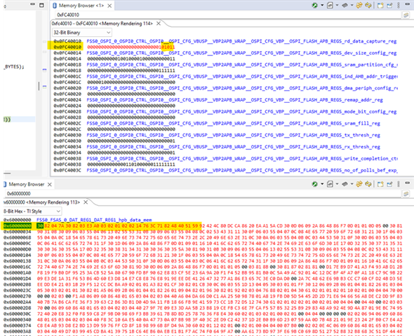
3. Modify ospi_flash_dma.c file to fill the gOspiFlashDmaTxBuf array with all 0xFF

4. Debug the project and set a breakpoint at ospi_flash_dma.c:123.  Using an oscilloscope to capture the waveforms of OSPI_CLK and OSPI_DQ4.

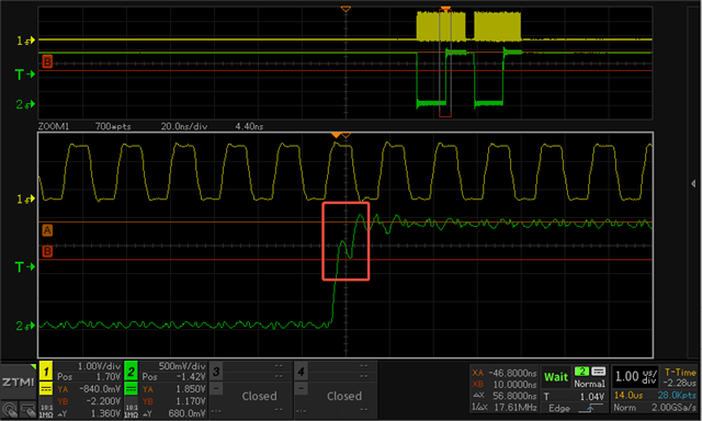
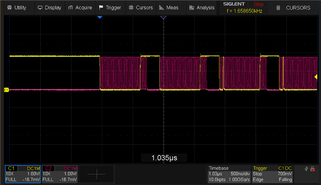
5. Continue runing the project and we can capture the half-level waveform for OSPI-READ. 1=CLK, 2=DQ4

  • Hi liang lu,

    I will also look onto this. I will need 1-2 days to respond.

    Regards,

    Stan

  • Hi Stanislav, Any update?

  • Hi Liang Lu,

    I'm expecting to have a better oscilloscope in a day or two. In the meantime, from your screenshot, I can only guess this could be a short bus contention due to improper timing.

    Regards,

    Stan

  • Hi Stanislav, any news?

  • Hi Liang Lu,

    Sorry for late response. I'm out of office and my team mate is having troubles with his PC. We will come back as soon as possible.

    Thanks,Stan

  • Hi Stan, another week has passed. When is it expected to be updated.

  • Hello Liang Lu,

    Stan is currently out of office.

    So far I could not manage to capture (with the new oscilloscope) the OSPI_DQ4 half-level (first bit) waveform for OSPI-READ scenario on the SK-AM64B.

    I will try to approach another TI internal team that can help us with more precise measurements. 

    I hope we can get back to you with new images in 2 or 3 days.

    Kind Regards,

    Anastas Yordanov

  • Hi Anastas , Stan:

         Any news?

    So far I could not manage to capture (with the new oscilloscope) the OSPI_DQ4 half-level (first bit) waveform for OSPI-READ scenario on the SK-AM64B.

    Have you referred to my example above to modify the code for verification? To trigger this phenomenon, it is necessary to ensure that the first byte received corresponds to a bit value of 1. Additionally, the flash chip's configured dummy time should be 1 cycle shorted than the value set in the SOC,Example:

  • Hi Liang Luo,

    Sorry for delayed response. May I ask you a couple of questions?

    1. In the original thread, Tony Tang says "Can capture it during OSPI booting also." Is this correct? We didn't see the half-level issue during OSPI boot.

    2. The waveform capture from the current thread:

    Differs from the waveform from the original thread:


    Is this now another issue or it is the same half-level issue captured with another possibly slower scope?

    Thanks,

    Stan

  • Hi Stan,

    We checked again: 

    Without half-level when load sbl, and with half-level when load application.

    So it seems that fsbl has adopted effective methods to avoid this issue.

    1. In the original thread, Tony Tang says "Can capture it during OSPI booting also." Is this correct? We didn't see the half-level issue during OSPI boot.

    We think it's the same issue.

    2. The waveform capture from the current thread:
  • Hi Liang Luo,

    Thank you. Please expect my reply early next week.

  • Hi Stan, any news?

  • Hi Liang Luo,

    I would like to apologize for delaying my response.

    The measurement setup took me a bit more time than expected.

    I used the TI SDK: mcu_plus_sdk_am64x_11_00_00_15.

    The flash memory used in the SK-AM64B - S28HS512T is a bit different than the one used in AM243x EVM -  S28HL512T, but generally I did not notice any difference in the key parameters you had a focus in this and previous thread.


    I did your recommended modifications in the:

    1) extern.syscfg - where I disabled the PHY Mode.

    2) I modified the data in ospi_flash_dma.c (line 413) to 0xFFFFFFFFu

    3) Added the breakpoint on the line: Ln123:  "CycleCounterP_reset()" of the ospi_flash_dma.c

    I managed to capture 3 DMA data transfers in total, so generally it looks like:

    I captured the phenomenon in the below screenshots. Within the first DQ4 data bit duration, the line retains its level at 1.32V for approx. 7 - 8 ns after the initial rising and then the signal continues to rise up to 1.8V.

    The OSPI CLK line frequency is around 41 MHz. ( ~ 166.666 MHz / 4)

    I confirm I do not observe the first bit half-level effect when I run the default_sbl_null bootloader.

    Kind Regards,

    Anastas Yordanov

  • I captured the phenomenon in the below screenshots. Within the first DQ4 data bit duration, the line retains its level at 1.32V for approx. 7 - 8 ns after the initial rising and then the signal continues to rise up to 1.8V

    This is what we call the half-level problem.

    The default_sbl_null don't access the flash, and indeed there is no half-level issue when fsbl loads the sbl. Therefore, I gussest you compare the flash configuration differences between the fsbl and sbl/app to see if that can resolve the problem.

  • Hi Liang Luo,

    Thanks for the clarification. Then I have to perform the tests with the OSPI SBL indeed. Surprisingly I can successfully flash but can not successfully run the sdk provided OSPI_SBL with an example application. I have started an internal thread to resolve this.

    From the AM64x SDK documentation:

    AM64x SDK Documentation NULL SBL

    I understood that although the NULL SBL is run from the OSPI Flash (OSPI Boot Mode), it only initializes cores and other peripherals but does not make cores load & execute any code from the OSPI Flash. 

    Before such a Flash related sysconfig comparison between fsbl/sbl/app images can be performed: I need to make sure we are aligned on the following understanding:

    FSBL -

     1. I understand that the "FSBL" is actually the AM243x / AM64x ROM Bootloader (i.e. the SoC ROM Resident Code). Is this correct ? 

    From your statement:

    The default_sbl_null don't access the flash, and indeed there is no half-level issue when fsbl loads the sbl. Therefore, I gussest you compare the flash configuration differences between the fsbl and sbl/app to see if that can resolve the problem.

    2. So far I myself have observed that the OSPI half-level read issue manifests itself during the application execution. (as I do not have observations on the OSPI SBL yet). I understand that you do not observe any OSPI half-level read issue when FSBL loads (transfers) the ospi SBL code from OSPI Flash offset 0x0 to on-chip RAM before execution. Correct ?

    3. Can you confirm that you observe the OSPI half-level read issue during the time when the OSPI SBL loads (transfers) the application from OSPI Flash offset 0x80000 to on-chip RAM before the application is executed ?

    Thanks

    Kind Regards

    Anastas Yordanov

  • 1. Yes,it's called RBL(Primary Bootloader) in your TRM.

     1. I understand that the "FSBL" is actually the AM243x / AM64x ROM Bootloader (i.e. the SoC ROM Resident Code). Is this correct ? 

    From your statemen

    2.Yes. Without half-level, and the frequency = 25MHz.

    I understand that you do not observe any OSPI half-level read issue when FSBL loads (transfers) the ospi SBL code from OSPI Flash offset 0x0 to on-chip RAM before execution. Correct ?

    3.With half-level when the SBL loads the application from OSPI Flash.

    Can you confirm that you observe the OSPI half-level read issue during the time when the OSPI SBL loads (transfers) the application from OSPI Flash offset 0x80000 to on-chip RAM before the application is executed ?
  • Liang,

    This is looking like two separate issues based on waveforms with different behavior. But would like to ask some additional information to confirm.

    This captured waveform appears to be a reflection on a transmit since the signal dips instead of being maintained at a near mid supply level. I expect this is an AM243x write being measured at the far end.

    Can you confirm if the above is also measuring  the first bit of read data or is this capture a transmit/write from the AM243x device?

    This behavior is different as it is held constant at a mid supply step. This would indicate one of two potential possibilities to me.

    1) The measurement point being at the flash is capturing an expected reflection. When measuring LVCMOS signals at the source end there will be a mid supply step as the signal transfers until it reflects back and fully transitions to VDD.

    2) There is bus contention where both the AM243x device and the flash device are trying to drive the bus resulting in mid supply. I would expect this to only occur on the first read cycle and this can be adjusted by configuring dummy cycles as indicated in the previous thread.

    It is hard to tell but it seems like this mid supply is in every rising edge on a read

    It is important to understand that measuring at the flash device is the correct point for measuring AM243x writes, but will cause distortion on reads when the flash is driving the signal.

    If it is possible to measure a read cycle at the AM243x boundary it will be a helpful data point. If the mid supply step is eliminated it can be confirmed this is a measurement artifact. If it continues, the focus should be on dummy cycle configuration and eliminating bus contention.

    Thanks,

    Chris

  • Hi Chris,

    Modifying the dummy cycle can eliminate this half-level but incorrect data will be read.  This was already elaborated in our previous topic: https://e2e.ti.com/support/microcontrollers/arm-based-microcontrollers-group/arm-based-microcontrollers/f/arm-based-microcontrollers-forum/1477203/am2434-ospi-read-command-first-bit-half-level-question/5739028?tisearch=e2e-sitesearch&keymatch=%20user%3A589657

    I also lack adequate conditions to test the signal from the AM243X proximal end. If it were signal reflection, shouldn't it occur every time the bit transitions from low to high? In addition, there is no half-level on the DQS pin. So  I think the possibility of signle reflection is relatively low.

    If it is possible to measure a read cycle at the AM243x boundary it will be a helpful data point

  • Liang,

    Yes if the pink trace is measured at the flash and is DQS driven by the flash then I agree it would show the same behavior. Since it does not and based on the discussion in the previous thread it does appear related to dummy cycles and resulting bus contention. We will need to involve SW teams as this will likely require SW modification to resolve.

    Thanks,

    Chris

  • Chris, Thanks.

    Is there an expected response & resolution timeline? Additionally, we hope to understand root cause of this issue later.

  • Hi Liang,

    I have been assigned this thread and will take this forward if this requires software tweaks.

    Allow me a day to come back to you with further updates.

    Thanks for your patience.

    Vaibhav

  • Hi Vaibhav,  if any update?

  • Hi,

    To get more updated SW configuration insights on this(apart from the earlier thread which Tony Tang created), please fill up the below table:

    TBF​

    Clock Frequency(OSPI SysConfig Setting) Clock Divider(OSPI SysConfig Setting) PHY Enable(Note: If PHY Enable is checked, then we are referring to DQS bit being set to 1) or Tap Mode of Operation? DMA Enable Dummy Cycles(Read) Waveform First Bit Half Level Seen? Functionality Broken? AM243 MCU+ SDK version
    TBF(To be filled) TBF TBF TBF TBF TBF TBF TBF
    TBF TBF TBF TBF TBF TBF TBF TBF
    Add More Rows If needed

    Looking forward to your response.

    Thanks,

    Vaibhav

  • What do you mean? Do I need to fill out the form again?

    I’ve already sent you the method to reproduce the issue—you can replicate the problem yourselves. Can’t you even do the most basic summary?

    We’ve been going back and forth on this issue for two months. Are we starting over now? Was all the communication over the past two months just wasted effort?

    Is the efficiency always this low? Every time, it's only when I push that there's a little progress.

  • Hi,

    The above table would have been used as a SW summary.

    Please tell me the bootmode in which you are booting? Is it xSPI/OSPI/SPI bootmode, refer TRM section 5.4.1 to be more specific on the bootmode pin configurations B3 - B9

    I saw you wrote 25 MHz, but that did not mention the bootmode. I am asking this so that I can go ahead and compare the following:

    Therefore, I gussest you compare the flash configuration differences between the fsbl and sbl/app to see if that can resolve the problem.

    Looking forward to your response.

    Thanks,

    Vaibhav

  • I’ve already sent you the method to reproduce the issue—you can replicate the problem yourselves. Can’t you even do the most basic summary?

    The problem was replicated as per the above responses, hence we need the bootmode configuration to compare the differences in the registers.

    Note, as per the replication, the issue was seen as described here:

    I captured the phenomenon in the below screenshots. Within the first DQ4 data bit duration, the line retains its level at 1.32V for approx. 7 - 8 ns after the initial rising and then the signal continues to rise up to 1.8V.

    Moreover, from the earlier thread: https://e2e.ti.com/support/microcontrollers/arm-based-microcontrollers-group/arm-based-microcontrollers/f/arm-based-microcontrollers-forum/1477203/am2434-ospi-read-command-first-bit-half-level-question/5739028?tisearch=e2e-sitesearch&keymatch=%20user%3A589657

    we have information on frequency, but filling up other factors would have helped in the table.

  • On the EVM board, we followed the EVM_SETUP_PAGE document guidelines to use the OSPI boot mode (which should actually be xSPI), with other configurations including the OSPI frequency set entirely to default values.


    On our own board, we have used both xSPI and SPI boot modes.

  • Hi,

    On our own board, we have used both xSPI and SPI boot modes.

    Assuming both xSPI and SPI bootmodes do not cause an issue with respect to waveform showing half level issue, I am going to compare the OSPI Configuration registers for RBL and the application.

    Please expect responses in sometime. Thanks for your patience.

    Thanks,

    Vaibhav

  • Hi Liang,

    I acknowledge the delay caused due to other high priority issues.

    Please expect responses as soon as I have some findings on this.

    Regards,

    Vaibhav

  • i2189? In fact, whether the phy mode is used or not, an additional dummy cycle is required

  • Hi Liang,

    Assuming both xSPI and SPI bootmodes do not cause an issue with respect to waveform showing half level issue, I am going to compare the OSPI Configuration registers for RBL and the application.

    I am running this experiment today and will update you with the results by end of today.

    Thanks,

    Vaibhav

  • Here are the register values for OSPI.

    Just after ROM boots the values are as follows:

    OSPI FLASH IO Application with PHY and DMA enabled just after Board_driversOpen:

    Allow me sometime to see the difference in these.

  • Hello Vaibhav,

    Is there update?

  • Hi,

    Thanks for your patience.

    I have reviewed the differences.

    Some of them of importance being: 

    ROM:

    dummy cycles: 20

    DELAY_FLD bit value = 1

    OSPI FLASH IO:

    dummy cycles = 25

    DELAY_FLD bit value = 1

    Can you please try this commit and build the example. Please see if the half level issue is still seen with the changes in the commit:https://github.com/TexasInstruments/mcupsdk-core-k3/commit/490656d87db71516007f6b23fadca60ab3feffb2

    Looking forward to your response.

    Thanks,

    Vaibhav

  • Have you verified it? I tried and it didn't work.

  • Can you please try this commit and build the example. Please see if the half level issue is still seen with the changes in the commit:https://github.com/TexasInstruments/mcupsdk-core-k3/commit/490656d87db71516007f6b23fadca60ab3feffb2

    Looking forward to your response.

    Since TI replicated the issue on EVM, I would suggest TI prove it before let customer try. the issue is pended for long already.

  • Hi Tony, Liang,

    I have started an internal discussion with HW and SW teams to fast track on this issue.

    I will share with you updates as we progress.

    Regards,

    Vaibhav

  • Hi Liang,

    Some observations based on debug I had with the SW team.

    When PHY mode is not checked(enabled) in the SysConfig GUI:

    Controller side Dummy Clocks (Read) should be equal to Flash side Dummy Clocks (Read).

    When PHY mode is checked(enabled) in the SysConfig GUI:

    Controller side Dummy Clocks (Read) should be 1 more than the Flash side Dummy Clocks (Read).

    If the value of clock frequency/divider <= 25 MHz, the Dummy Clocks (CMD) = 3

    If the value of clock frequency/divider > 25 MHz and <= 50 MHz, the Dummy Clocks (CMD) = 4

    Regards,

    Vaibhav

  • Hi Liang, Tony,

    Can you help classify the above waveform based on the following points?

    There are two issues that happen on the OSPI interface:

    • Bus contention – flash and SOC driving the bus at the same time will result in sustained mid level signal. Likely only first transfer.
    • Reflection – voltage actually drops below and shows some signs of ringing. Related to layout/trace length/board design. Can be helped with layout changes and potentially increasing drives strength. Will occur on ever low to high transaction.

    Looking forward to your response.

    Thanks,

    Vaibhav

  • Hi Vaibhav,

    When PHY mode is not checked(enabled) in the SysConfig GUI:

    Controller side Dummy Clocks (Read) should be equal to Flash side Dummy Clocks (Read).

    How you test this? If equal, incorrect data will be read.

    When PHY mode is checked(enabled) in the SysConfig GUI:

    Controller side Dummy Clocks (Read) should be 1 more than the Flash side Dummy Clocks (Read).

    If the value of clock frequency/divider <= 25 MHz, the Dummy Clocks (CMD) = 3

    If the value of clock frequency/divider > 25 MHz and <= 50 MHz, the Dummy Clocks (CMD) = 4

    Why? The purpose of starting this thread is to understand the reasons behind such a configuration and how to resolve the half-level issue.

  • Hi Liang, Tony,

    Can you help classify the above waveform based on the following points?

    Refer to the previous reply as show below.

    Hi Chris,

    Modifying the dummy cycle can eliminate this half-level but incorrect data will be read.  This was already elaborated in our previous topic: https://e2e.ti.com/support/microcontrollers/arm-based-microcontrollers-group/arm-based-microcontrollers/f/arm-based-microcontrollers-forum/1477203/am2434-ospi-read-command-first-bit-half-level-question/5739028?tisearch=e2e-sitesearch&keymatch=%20user%3A589657

    I also lack adequate conditions to test the signal from the AM243X proximal end. If it were signal reflection, shouldn't it occur every time the bit transitions from low to high? In addition, there is no half-level on the DQS pin. So  I think the possibility of signle reflection is relatively low

  • There are two issues that happen on the OSPI interface:

    • Bus contention – flash and SOC driving the bus at the same time will result in sustained mid level signal. Likely only first transfer.
    • Reflection – voltage actually drops below and shows some signs of ringing. Related to layout/trace length/board design. Can be helped with layout changes and potentially increasing drives strength. Will occur on ever low to high transaction.

    Looking forward to your response.

    What kind of response do you want from customer and me? 

    We reported the issue, need BU team analysis, you kick the ball back to us to analysis?

    If need my option, I think it is Bus contention, because modify the dummy cycle number can eliminate the first bit middle level abnormal signal, but result is wrong. so I think it may related to the IP, suggest you work with IP vendor to analysis. 

    It is not reflection definitely, because modify the dummy cycle eliminate the middle level signal.

    Since BU team reproduced the issue on EVM already, BU can verify ideas on EVM and provide conclusion to customer.

  • Hi,

    Upon running the steps as mentioned by Liang.

    I have flashed default_sbl_null.cfg file on the AM243-EVM. And then upon loading the OSPI FLASH DMA via CCS and putting a breakpoint at line 123(with Phy disabled), I see that the first bit of DQ4 is as attached in the above diagram.

    I am not seeing the half level issue as seen by Anastas and Liang. My next step is see how Anastas ran the setup differently compared to mine.

    Thanks,

    Vaibhav

  • Hi Vaibhav,

    I think your waveform also reproduces the issue; otherwise, the voltage level of the first clock wouldn't drop this much. It's possible that your oscilloscope's performance is poor or it isn't grounded with the product, which might be why the waveform isn't very clear.

    Additionally,

    1. How you test this? I tried and receive incorrect data

    When PHY mode is not checked(enabled) in the SysConfig GUI:

    Controller side Dummy Clocks (Read) should be equal to Flash side Dummy Clocks (Read).

    2. Have you confirmed that this isn't the cause?

    I acknowledge the delay caused due to other high priority issues.
  • Hi Liang,

    I ran some experiments. I do not see any bus contention and the erase, writes and reads happen correctly as well.


    With the same dummy cycles read setting of 24 on the Controller and 24 on the Flash side, I am able to read the values.


    I have debugged this and found out the following observation: (In SysConfig for OSPI FLASH DMA, have both Controller and Flash read cycles set as 24)


    1. In Flash_norOspiOpen function, we firstly set the readDataCapDelay value while reading the device and manufacture id. (no action required for this step by the customer, just explaining the flow.)
    2. Post this step, while in application, ask the customer to put a breakpoint at the following line:
    3. This will ensure that the DAC is enabled. Now, in memory browser go the address 0x60000000. Here you will see the bootloader image flashed and it should begin with something like 30 82 .. .. .. and so on.
    4. You will find out that the bootloader image is bit jumbled up with a bunch of “00 00”s in between. I see this in my setup.
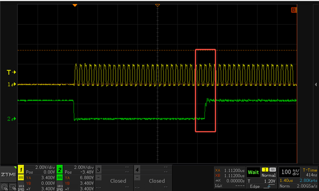
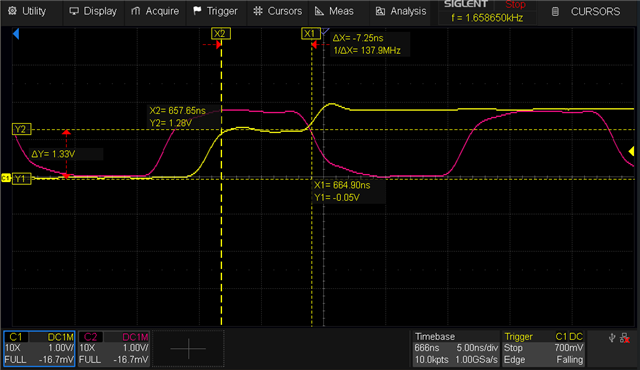
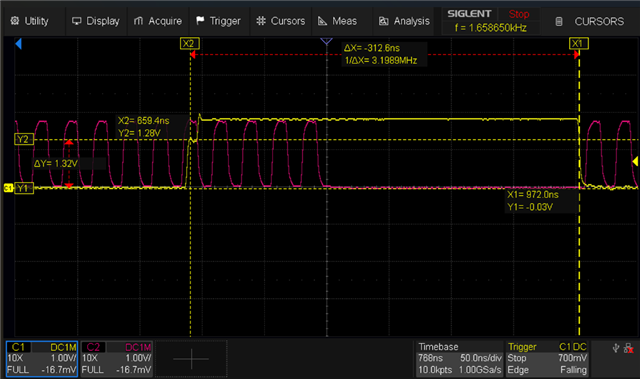
       (image got flipped when I took a screenshot due to some glitch)
    5. I figured out this might be a readDataCaptureDelay problem.
    6. So, I changed the value of the register 0xFC40010 bits[1:4] to 5 and it worked for me. Previously bits [1:4] was configured as 1, now the updated value I wrote was 5, so now with bits[1:4] as value 5, I see the correct contents as shown in the image below:
    7. I would like you to test with values from 15 until 0, and tell me which value gives them the correct contents at 0x60000000.


    Next Steps:


    If this is replicated at the customer’s setup, then the next steps can be suggested.

    Looking forward to your response.

    Thanks,

    Vaibhav

  • Hi Vaibhav, 

    I tested on EVM board, and bit[1:4] = 4 or 5 is OK, other value NOK.

    Next Monday, I'll test our own board to see if the effect is consistent

  • Hi Liang,

    I will wait for your results on Monday.

    Please have 24 and 24 dummy cycles as mentioned in the steps above and follow the same for your own(custom) board as well.

    If not 5, then try for other values as well from 15 until 0.

    Looking forward to it.

    Thanks,

    Vaibhav

  • Hi Vaibhav, on our board(S28HL256T/S28HL512T), 5 and 6 is OK, other value is NOK.

  • Hi Liang,

    The expert is currently out of office and will be back on Thursday. Responses to this thread will be delayed. Please ping the thread if you don't get response by end of this week.

    Regards,

    Tushar

  • Hi Vaibhav,

       Is there a final solution, specifically how to modify the code? Is there a plan to update the SDK and Errata to optimize this issue?