This thread has been locked.

If you have a related question, please click the "Ask a related question" button in the top right corner. The newly created question will be automatically linked to this question.

Stellaris LM3S1968-Board isn't working.

Other Parts Discussed in Thread: LM3S1968

Hi everyone,

My Stellaris LM3S1968 stopped working after setting the clock speed to 2MHz from an original 8MHz (line 14 of the SSCCE, line 87 of the pastie). When I try to run anything it gives the following errors now:

LMI device check failed, bad part number detected.
CORTEX M30: Error connecting to the target.

#include "inc/hw_memmap.h"
#include "inc/hw_types.h"
#include "driverlib/gpio.h"
#include "driverlib/sysctl.h"
#include "driverlib/systick.h"
#include "driverlib/debug.h"
#include "drivers/rit128x96x4.h"
#include "stdio.h"

#define SAMPLE_RATE_HZ 200000

void initClock (void) {
    
    SysCtlClockSet(SYSCTL_SYSDIV_10 | SYSCTL_USE_PLL | SYSCTL_OSC_MAIN |
          SYSCTL_XTAL_8MHZ);
    
    SysTickPeriodSet(SysCtlClockGet() / SAMPLE_RATE_HZ);
	
}

void initDisplay(void) {
	  RIT128x96x4Init(1000000);
}

void displayValues(void) {
    
    RIT128x96x4StringDraw("Works", 5, 5, 15);

}

int main(void) {
	initClock();
}

I think this is a SSCCE (can't test it as the board isn't working) -- full code @ http://pastie.org/9125726

Does anyone know what I've done wrong or how to fix it? It is replicable (I have done it to two boards, trying to figure it out) so please be careful if changing that 8 to 2 MHz.

Thanks in advance!

  • Hi Matt,

        Try the LM Flash Programmer Debug Port Unlock Utility. Select "Fury" Class. 

        JTAG Communication Failures

    -kel

  • Matt Barton said:
    stopped working after setting the clock speed to 2MHz from an original 8MHz

    Read your post 3 times - still unclear what you're trying to convey.  (you surely know - but hasn't penetrated my thick skull)

     SysCtlClockSet(SYSCTL_SYSDIV_10 | SYSCTL_USE_PLL | SYSCTL_OSC_MAIN |
              SYSCTL_XTAL_8MHZ);

    Function call above should yield a 20MHz "system clock" - provided the on-board xtal is indeed 8MHz.  If that xtal is 8MHz - and you changed that, "SYSCTL_XTAL_8MHZ" to, "SYSCTL_XTAL_2MHZ" - that fact would have, "done you in!"

    I believe that, "SYSCTL_SYSDIV_100" would yield your 2MHz system clock - although that speed is unusual.

    As with most things "ARM" Devil is in the detail - your 2 & 8 MHz desire/implementation is not as clear as it could be...

  • When running the unlock utility, I am getting this error. I will try this again if I'm able to
    install the LM Flash Programmer at school tomorrow.

    ~ Matt

  • Hi,

       I suggest you use the latest version of LM Flash Programmer for this Debug Port Unlock task. Also, if you are going to try at another PC, make sure that the ICDI drivers are installed.

    -kel

  • cb1- said:

    stopped working after setting the clock speed to 2MHz from an original 8MHz

    Read your post 3 times - still unclear what you're trying to convey.  (you surely know - but hasn't penetrated my thick skull)

     SysCtlClockSet(SYSCTL_SYSDIV_10 | SYSCTL_USE_PLL | SYSCTL_OSC_MAIN |
              SYSCTL_XTAL_8MHZ);

    Function call above should yield a 20MHz "system clock" - provided the on-board xtal is indeed 8MHz.  If that xtal is 8MHz - and you changed that, "SYSCTL_XTAL_8MHZ" to, "SYSCTL_XTAL_2MHZ" - that fact would have, "done you in!"

    I believe that, "SYSCTL_SYSDIV_100" would yield your 2MHz system clock - although that speed is unusual.

    As with most things "ARM" Devil is in the detail - your 2 & 8 MHz desire/implementation is not as clear as it could be...

    [/quote]

    In hindsight, changing the divisor would have been a better idea than changing the xtal speed.
    I'm unsure as to why this would be giving 20MHz though; 8MHz/10 would yield 800 Hz, unless
    I've forgotten fundamental mathematics.

    The reason that this was changed is because for a project, I need to get the pulse width
    modulator to output a frequency of 150Hz and with the clock speed at what it was, could only
    get it to at least 160Hz.

    The rationale for that was .. if it can't get low enough because the clock is too fast, change the
    clock speed.

    Anyways, sorry if the question was unclear. I will see if the Unlock Utility will work when I'm at
    school tomorrow.

    Thank you for the replies, cb1-, -kel. :)

  • Matt Barton said:
    I'm unsure as to why this would be giving 20MHz though; 8MHz/10 would yield 800 Hz, unless
    I've forgotten fundamental mathematics.

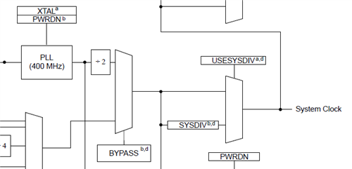
    It does not work that way. You, need to refer to the datasheet regarding system clock. See, below from LM3S1968 datasheet. Since, you are using the PLL the equation is 400MHz / 2 / 10 = 20 Mhz.

    LM3S1968 Main Clock Tree

    -kel

  • Hi Matt,

    Please review your data sheet, page 190, RCC register - has a bit USEPWM which enables a pre-scaler PWMDIV with up to /64 capability - just to make easy your life - so you can choose a higher clock.

    Petrei

  • Petrei said:
    enables a pre-scaler PWMDIV with up to /64 capability - just to make easy your life

    Surely does, "ease poster's life."  But - does that come with any price?

    Doubtful that this impacts the (expected) simple requirement here - but the "granularity" of the resulting PWM output is reduced - and thus any such use of  "PWMDIV" first deserves some care & analysis...

    On the plus side - Petrei's suggestion indeed "frees" the MCU from extensive, "throttle shut-down" - thus enabling other program aspects to run/exe at normal MCU speed...