This thread has been locked.

If you have a related question, please click the "Ask a related question" button in the top right corner. The newly created question will be automatically linked to this question.

Problem with Keil + PWM at EK-TM4C123GXL LaunchPad

Other Parts Discussed in Thread: EK-TM4C123GXL, TM4C123GH6PM, TM4C1231C3PM, LMFLASHPROGRAMMER

Hi!

I'm stucked programming with Keil environment as I didn't find any PWM example code for the EK-TM4C123GXL LaunchPad board.

I found some interesting code for Code Composer Studio (CSS) but I can't use it in Keil, could you give me some tips to do so?

Specifically it's about this Labs at TM4C123G_LaunchPad_Workshop:

http://processors.wiki.ti.com/index.php/Getting_Started_with_the_TIVA%E2%84%A2_C_Series_TM4C123G_LaunchPad

and the labs that are inside:

http://software-dl.ti.com/trainingTTO/trainingTTO_public_sw/GSW-TM4C123G-LaunchPad/TM4C123GLaunchPadWorkshopSetup.exe

I'm trying to use the PWM code in Keil but I can't use it.

Even better if you have code to run a PWM module in the EK-TM4C123GXL LaunchPad board.

Thanks!

P.S.: after searching several days in Internet for a solution for PWM module at a EK-TM4C123GXL LaunchPad board I didn't find any solution for Keil, so I think it needs a proper and good solution.

  • Hello Francisco,

    As mentioned in the earlier thread, if you can check the examples in TIVWare 2.1.0

    C:\ti\TivaWare_C_Series-2.1.0.12573\examples\peripherals\pwm

    That should help you out. If you can send in your requirements then may be I can help suggest changes to the PWM example in the TIVAWare installation and help build it in Keil. Of course this may take time as I have two threads to close as well where community members need to get going....

    Regards

    Amit

  • Hello Amit,

    I prepared the most simple project in Keil, actually it has just the starter files and one PWM example to check it:

    • startup_TM4C123.s
    • system_TM4C123.c
    • and reload_interrupt.c from the folder you told me...

    But I get errors and warnings messages when compiling:

    Build target 'Target 1'

    compiling reload_interrupt.c...
    reload_interrupt.c(115): error: #20: identifier "GPIO_PA0_U0RX" is undefined
                GPIOPinConfigure(GPIO_PA0_U0RX);
    reload_interrupt.c(116): error: #20: identifier "GPIO_PA1_U0TX" is undefined
                GPIOPinConfigure(GPIO_PA1_U0TX);
    reload_interrupt.c(314): warning: #223-D: function "INT_RESOLVE" declared implicitly
                IntEnable(INT_PWM0_0);
    reload_interrupt.c(314): error: #20: identifier "INT_PWM0_0_" is undefined
                IntEnable(INT_PWM0_0);
    reload_interrupt.c: 1 warning, 3 errors
    ".\EjemploPWM.axf" - 3 Error(s), 1 Warning(s).
    Target not created

    Can you tell me what's going on? It looks like I miss some declarations but I don't know how to solve it. Thanks again!

    Francisco

  • Francisco Dominguez1 said:
    It looks like I miss some declarations but I don't know how to solve it

    Those errors are occurring because the predefined macro name which tells the TivaWare include files the Tiva part in use has not defined.

    The required format of the predefined name is PART_<device_id>. i.e. for the TM4C123GH6PM device used on the EK-TM4C123GXL LaunchPad, the predefined symbol PART_TM4C123GH6PM should be given to the compiler.

    [I don't use Keil, so am unsure how to do that with the Keil compiler]

  • Hello Francisco,

    In addition to what Chester has already mentioned also use the predefined symbol TARGET_IS_XXX_YYY where

    XXX is TM4C123 or TM4C129: In your case it is TM4C123

    YYY is the revision of the device which can be found out from the SYSCTL.DIDO register and the look up table exist in the Data sheet. For the EK platfom it would be revion 7 and would translate as RB1

    Thus, the above define would be TARGET_IS_TM4C123_RB1

    Regards

    Amit

  • Thanks Chester and  Amit!

    After inserting:

    #define TARGET_IS_TM4C123_RB1

    I have only two errors left! :-)

    This is my compilation message:

    Build target 'Target 1'
    compiling reload_interrupt.c...
    reload_interrupt.c(116): error: #20: identifier "GPIO_PA0_U0RX" is undefined
                   GPIOPinConfigure(GPIO_PA0_U0RX);
    reload_interrupt.c(117): error: #20: identifier "GPIO_PA1_U0TX" is undefined
                   GPIOPinConfigure(GPIO_PA1_U0TX);
    reload_interrupt.c: 0 warnings, 2 errors
    ".\EjemploPWM.axf" - 2 Error(s), 0 Warning(s).
    Target not created

    So I guess there are two GPIO pins to configure for the UART function that I didn't:

    GPIO_PA0_U0RX

    and

    GPIO_PA0_U0TX

    Can be that? Can I assign any UART Pins from the microcontroller?

    Thanks!

    Francisco

  • Hello Francisco,

    Please include "driverlib/pin_map.h"

    Regards

    Amit

  • Hi Amit,

    Thanks for the suggestion. I did it already as the PWM example file "reload_interrupt.c" from TivaWare_C_Series-2.1.0.12573 has it already as the other include ones:

    #include <stdbool.h>
    #include <stdint.h>
    #include "inc/hw_ints.h"
    #include "inc/hw_memmap.h"
    #include "driverlib/gpio.h"
    #include "driverlib/interrupt.h"
    #include "driverlib/pin_map.h"
    #include "driverlib/pwm.h"
    #include "driverlib/sysctl.h"
    #include "driverlib/uart.h"
    #include "utils/uartstdio.h"

    (that are also in the TivaWare_C_Series-2.1.0.12573 drivers you told me before)

    Any other ideas?

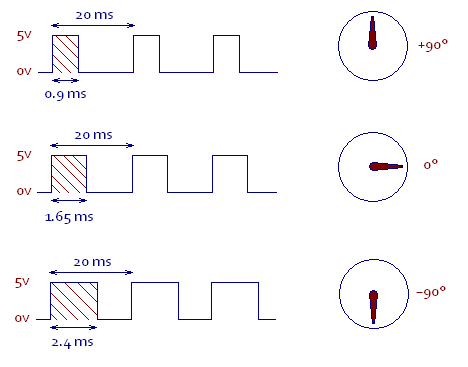
    BTW you told me about specific application: at this moment I need a driver to handle a standard hobby servo by PWM (like this http://www.pitt.edu/~sorc/robotics/handbook/ServoControl.htm). So just a routine to send a duty cicle is fine. Then I can use it with other PWM outputs and variations. Thanks!

    Kind regards,

    Francisco

  • Hello Francisco,

    Can you zip the project and send it across? Also what is the Duty Cycle and Timer Period for the particular Servo motor so that I can tune the test for you.

    Regards

    Amit

  • Hi Amit,

    Attached you have the whole project. I included the libraries so you just have to adjust the directories from the first part in the "reload_interrupt.c" main program.

    At the beginning is enough to have the Timer Period of 20ms (servo motor period)  and a Duty Cycle of 1.5ms:

    http://i.stack.imgur.com/knRt8.jpg

    When it'll work I will change for variables and change them as needed. Thanks! 

    6837.Projects.rar

    Francisco

  • Hello Francisco,

    The TM4C123,h file is missing in the zipped project. Also I found out what the issue is with the compiler.

    In the options for defines the part define has been put as TM4C123GH6PM. Instead it should be PART_TM4C123GH6PM

    Regards

    Amit

  • Hi Amit,

    You are right even the file TM4C123.h was in the includes directory for the options in Keil. I inserted also in the new project's folder and Zip file:

    1108.Projects.zip

    Where do you mean the "options for defines the part define"...? Do you mean at the beginning of the reload_interrupt.c file ?

    Just in case I inserted this after #includes:

    #define PART_TM4C123GH6PM

    Also I inserted these two defines:

    #define GPIO_PA0_U0RX 0x00000001
    #define GPIO_PA1_U0TX 0x00000401

    Also some defines more that I inserted before some days ago:

    #define GPIO_PB6_M0PWM0 0x00011804
    #define GPIO_PB7_M0PWM1 0x00011C04
    #define GPIO_PB4_M0PWM2 0x00011004
    #define GPIO_PB5_M0PWM3 0x00011404
    #define GPIO_PE4_M0PWM4 0x00041004
    #define GPIO_PE5_M0PWM5 0x00041404
    #define GPIO_PF1_M1PWM5 0x00050405
    #define GPIO_PF2_M1PWM6 0x00050805
    #define GPIO_PF3_M1PWM7 0x00050C05

    And now I have 1 warning and 1 error when compiling! Here you have them:

    Build target 'Target 1'
    compiling reload_interrupt.c...
    reload_interrupt.c(318): warning: #223-D: function "INT_RESOLVE" declared implicitly
                   IntEnable(INT_PWM0_0);
    reload_interrupt.c(318): error: #20: identifier "INT_PWM0_0_" is undefined
                   IntEnable(INT_PWM0_0);
    reload_interrupt.c: 1 warning, 1 error
    ".\ProyectoPWM.axf" - 1 Error(s), 1 Warning(s).
    Target not created

    So, do you have any clue about this? Maybe you can try to compile it by yourself and have a look. Thanks!

    Francisco

  • Hi again Amit,

    Just to update you about some advancements.

    I accomplished to generate PWM signals with this board using this project: PWMDual_4C123.zip from http://users.ece.utexas.edu/~valvano/arm/

    I also could change PWM frequency already. Now it's time for Duty Cycle and some inputs to change it.

    Hi!


    Just to update you and thank you! I finally generate PWM signals with the module and the software PWMDual_4C123.zip from http://users.ece.utexas.edu/~valvano/arm/ Thanks!

     You can follow up my improvements about PWM and other topics here:

    http://letsmakerobots.com/content/lets-learn-basics-robotics-edxs-embedded-systems-shape-world

    Thank you very much again!

    Francisco

  • Hello Francisco,

    So is this thread closed and all your target goals met? Or is there something for me to still to complete/follow up?

    Regarda

    Amit

  • Hi Amit,

    Thanks for asking!

    Actually I have now to do the following with this PWM special routine:

    1. isolate the two PWM outputs, as they work together: they use the same period but with 180º of shift. I think it's a matter of changing the period when its's passed to each output register...
    2. know how to change the Duty Cycle: as its fixed to 50%. From other PWM routines I studied I think it has something to do with "PWM0_0_CMPA_R"...

    With this I will have the driver for two PWM to control their periods and duty cycles, and then I will try to do the same with all PWM the EK-TM4C123GXL LaunchPad has.

    If you can check the routine I sent attached just above in the message before and tell me some tips it will be very helpful. Thanks!

    Kind Regards,

    Francisco

  • Hello Fransico,

    I checked the latest project file you sent and it does not compile and gives error for SYSCTL definition missing.

    Build target 'Target 1'
    compiling system_TM4C123.c...
    system_TM4C123.c(527): error:  #20: identifier "SYSCTL" is undefined
          rcc  = SYSCTL->RCC;
    system_TM4C123.c(587): error:  #20: identifier "SYSCTL" is undefined
          SYSCTL->RCC2 = 0x07802810;    /* set default value */
    system_TM4C123.c: 0 warnings, 2 errors
    ".\ProyectoPWM.axf" - 2 Error(s), 0 Warning(s).
    Target not created

    Regards

    Amit

  • Hi Amit,

    I just downloaded the PWM package  PWMDual_4C123.zip and compiled fine.

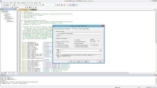
    Here you have a screen capture with the compilation messages. Please check that Define option in "Preprocessor Symbols" is the same: 

    rvmdk PART_TM4C123GH6PM

    Kind Regards,

    Francisco

  • Hello Francisco

    OK. I may have downloaded the project file before that. This one does compile fine. So if I get the requirements correctly then

    1. You want the two PWM outputs to be independent of each other? No relation between the two PWM signals

    2. And how to get Duty Cycle Changing...

    Regards

    Amit

  • Hi Amit,

    Good that you had a good compilation!

    Yes, those are the requirements. Thanks!

    Kind Regards,

    Francisco 

  • Hello Francisco,

    I have attached the project. I have yet not decoupled the two PWM but made the duty cycle changeable.

    The only way you can have the frequency independent for the two PWM is to use another PWM Generator and use PWM2/PWM3.

    4405.PWMDual_4C123.7z

    Regards

    Amit

  • Hi Amit,

    Thank you it works great!

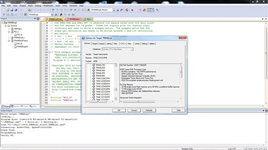
    I was checking some items and I found that you have selected device TM4C1231C3PM with this Tiva C board

    I changed to TM4C123GH6PM and it worked too.

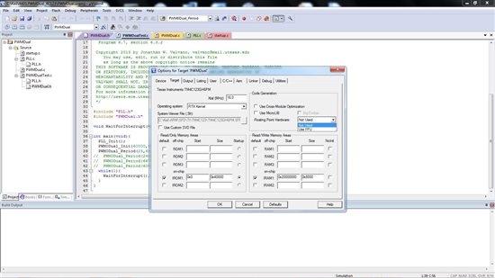
    Another strange thing is that FPU must be disabled in order to run fine in board:

    However I checked the TM4C123GH6PM datasheet and it says this in page 130:

    "The Cortex-M4F FPU fully supports single-precision add, subtract, multiply, divide, multiply and

    accumulate, and square root operations. It also provides conversions between fixed-point and
    floating-point data formats, and floating-point constant instructions. The FPU provides floating-point
    computation functionality that is compliant with the ANSI/IEEE Std 754-2008, IEEE Standard for
    Binary Floating-Point Arithmetic, referred to as the IEEE 754 standard."

    So I don't know why FPU can't be enabled... otherwise system does not work.

    Besides these curious topics, I tested the solution and both PWM0 and PWM1 work with two different duty cycle however I found some strange behaviour:

    (from now examples with pair vaules are dcpwm0 and dcpwm1

    • Duty cycles of 1,1 do nothing. It looks like same duty cycle in both PWM produces nothing.
    • Strange behaviour with limit values, like:
    • 99,0: PB6 nearly does not blink and PB7 does not blink at all.
    • 99,5: PB6 nearly does not blink and PB7 nearly always on.
    • 15,65: PB6 blinks more time on, PB7 little time on.
    • 5,65: PB6: nearly always on, PB7 nearly half time on.
    • 1,98: PB6: nearly always on, PB7 nearly always off.

    With this inputs I realize that:

    1. both duty cycle are working together.
    2. dcpwm0 acts on PB7 and dcpwm1 acts on PB6 in an inverse way.

    To correct this I use this change:

    PWM0_0_CMPA_R = (period*(101-dcpwm1))/100; // 6) count value when PWM1/PB7 toggles
    PWM0_0_CMPB_R = (period*(101-dcpwm0))/100; // 6) count value when PWM1/PB6 toggles

    Now:

    • Duty cycles of 1,2 make PB6 and PB7 blink the smallest amount of time.
    • However it looks like same duty cycle in both PWM produces nothing.
    • expected behaviour with limit values, like:
    • 99,0: PB6 nearly always on and PB7 off.
    • 99,5: PB6 nearly does not blink and PB7 nearly always on.
    • 15,65: PB6 blinks less time on, PB7 more time on.
    • 5,65: PB6: nearly always off, PB7 a bit more half time on.
    • 1,98: PB6: nearly always off, PB7 nearly always on.

    Now, with a period of 1250 I get 50Hz (period 20 ms) output in PB6 and:

    • and duty cycle of dcpwm0 = 12 a duty cicle of 12%: 2.4 ms which is -90º position for a servo
    • duty cycle of dcpwm0 = 8 a duty cicle of 8%: 1.6 ms which is nearly 0º position for a servo
    • duty cycle of dcpwm0 = 4 a duty cicle of 4%: 0.8 ms which is nearly -90º position for a servo

    With these calculations I attach a micro servo PWM input to PB6 and test it. It's a very low power servo so it can be powered from the 5V mains of the Tiva C board.

    Position for -90º is quite fine, but other positions can be tricky.

    I tried to divide dcpwm0 here to expand duty cycle range:

     PWM0_0_CMPB_R = (period*(100-dcpwm0/2))/100;       // 6) count value when PWM1/PB6 toggles

    but it didn't work that much, only a few steps more. But adjustment is too coarse...Even more, the servo tries to find neutral position after each change of setpoint or even it does not get it. Sometimes Keil gets frozen and I have to re-start Keil.

    So I returned to the former formulae you inserted:

    PWM0_0_CMPB_R = (period*dcpwm0)/100;       // 6) count value when PWM1/PB6 toggles

    And it works better from 98 to 89, but for lower values servo try too hard to find the final position, and adjustment is also too coarse.

    So I need to adjust duty cycle more exactly. Do you have any idea? Thanks!

    Kind regards and have a nice weekend.

    Francisco

  • Hello Francisco.

    I have defined the duty cycle as integer numbers only and not for fractional duty cycle. If that is what you want as control then, would take me some time to complete. Can you send your updated project?

    Regards

    Amit

  • Hi Amit,

    I did it! I could update the project so now it can handle properly a servo motor!

    You can read the whole documentation inside the main test routine, but here are the main description:

    This values are based on real test and calculations derived from them
    for Duty Cycle at "dcpwm0" value at "PWM0Dual_Period" PWM output function

    Position
    of servo in Calculated
    Degrees positions
    0 ---------- 2100 (or +90º as said above)
    45 ---------- 3466
    90 ---------- 4833 (or 0º as said above)
    135 ---------- 6199
    180 ---------- 7565 (or -90º as said above)

    1 degree ---------- 30

    As dcpwm0 and dcpwm1 are unsigned short variables 65535 is the maximum value for them
    But for PWM servo motor control change only dcpwm0 between values shown just above.

    You can download the project from there:

    2605.ServoMotorbyPWM_and_TM4C123.rar

    Now that this is solved, my next steps are:

    1. learn how to integrate this function in a bigger system, with an ADC input to measure positions and actuate on the servo. DONE! (see below)
    2. integrate more PWM servos to make a functional robot. NEXT.

    At this moment, if I try to integrate an ADC from another function that works already independently, project gives me several errors and warnings when compiling

    Errors solved via integration step by step and solving each error when occurs.

    Here is the project for servo motor control via potentiometer input:

    2100.ServoMotorbyPWM+ADC.rar

    Some refinements for this input function is trigger ADC by input interruption but at this moment actual way is fine.

    As said, next step is the integration of several servos and more sensors... Thanks for your help!

    Kind regards,

    Francisco

  • Hello Francisco

    That is great. You did it!!! Also the project post would be a useful resource to others you may wanting to be doing something similar.

    I would request to put ADC queries (if any) as a separate thread on the forum.

    Regards

    Amit

  • Hi Amit,

    Thanks! Yes I wished to find this routine before, but now here it is ;-)

    I also described and published it in Let's Make Robots website, at my Embedded Systems course's article. I also credited your help, I hope it's OK with you, if not just tell me.

    Amit Ashara said:
    I would request to put ADC queries (if any) as a separate thread on the forum.

    Do you mean to post in a separate thread of the forum the ADC routine? If you want I can answer it as I have already a routine for that.

    Kind regards,

    Francisco

  • Hello Francisco

    My point was in case you have problems with the ADC of TIVA, you could start a new thread. Since it is working I believe nothing is required.... Great to see the video's that you have posted as well.

    Regards

    Amit

  • Hi Amit,

    Ok, yes the ADC of Tiva works perfectly. We learnt a lot in this Embedded Systems course as you saw ;-)

    Nice you enjoyed my videos, I will do also one for the PWM servo control. By the way I hope also you liked my explanations about the course.

    Kind regards,

    Francisco

  • Hi Amit,

    New issue when compiling for next PWM output. This time is with PortD0 output. I just copied the PWM .c and .h driver file, changing registers to handle M1PWM0, and integratin it in the main test function.

    I have an error when compiling that I can't solve as there is too few information:

    Build target 'ServoMotorPWM+ADC'
    compiling PWMDualTest.c...
    linking...
    .\PWMDual.axf: Error: L6218E: Undefined symbol PWM1Dual_Init (referred from pwmdualtest.o).
    .\PWMDual.axf: Error: L6218E: Undefined symbol PWM1Dual_Period (referred from pwmdualtest.o).
    Not enough information to list image symbols.
    Finished: 1 information, 0 warning and 2 error messages.
    ".\PWMDual.axf" - 2 Error(s), 0 Warning(s).
    Target not created

    Here is the whole Project that gives the two errors:

    4137.ServoMotorsby2xPWM+ADC(potentiomenter).zip

    Is it possible to have more information from the compiler (in Keil) to solve the problem? Thanks!

    Kind regards,

    Francisco

  • Hello Francisco

    I see that the two functions are declared in PWMDual1.h file but where is the full function?

    Regards

    Amit,

  • Hi Amit,

    They are in PWMDual1.c

    I added both to the project's items and solved already compilation errors:

    Build target 'ServoMotorPWM+ADC'
    compiling PWMDual1.c...
    PWMDual1.c(87): error: #20: identifier "GPIO_PORTB_DEN_R" is undefined
    GPIO_PORTB_DEN_R |= 0x03; // enable digital I/O on PD1-0
    PWMDual1.c(93): error: #20: identifier "PWM0_1_GENA_R" is undefined
    PWM0_1_GENA_R = (PWM_1_GENA_ACTCMPBD_ZERO|PWM_1_GENA_ACTCMPBU_ONE);
    PWMDual1.c(109): error: #20: identifier "period2" is undefined
    PWM1_0_CMPA_R = (period2*(101-dcpwm3))/100; // 8) count value when PWM1/PD1 toggles
    PWMDual1.c(107): warning: #550-D: variable "period" was set but never used
    unsigned long period;
    PWMDual1.c: 1 warning, 3 errors
    ".\PWMDual.axf" - 3 Error(s), 1 Warning(s).
    Target not created

    Now it compiles fine, but system does nothing when downloaded to the Launchpad board.

    Here is the project updated:

    0654.ServoMotorsby2xPWM+ADC(potentiomenter)_V2.zip

    I think it can be any PWM register that I mismatched... Any suggestions? Thanks!

    Kind regards,

    Francisco

  • Hello Francisco,

    In the second set of PWM functions the configuration of GPIO's is not correct, I think based on the code, that you are using PWM-1 M0 and M1 channels on PD0 and PD1 but the PCTL is being set for PD7 and PD6

    Is PWM0 still working or not?

    Regards

    Amit

  • Hi Amit,

    Thanks! Nothing looks like working, even the Nokia display has many dots but nothing readable...

    Kind regards,

    Francisco

  • Hello Francisco,

    Since I do not have your setup, I would need to troubleshoot

    1. Is there is a bus fault? Check the NVIC_FAULTSTAT and NVIC_FAULTADDR register

    2. If by removing the new PWM channels function call you can get rest of the system to work, then we need to isolate it in the new functions being implemented.

    Regards

    Amit

  • Hi Amit!

    Good ideas!

    How can I check the NVIC_FAULTSTAT and NVIC_FAULTADDR register when running? (If that's what you mean above) I can't use Keil debugger with board and PWM, can I? I tried some days ago and it gave me error.

    I'll try also to isolate the new function by deactivation and see if the rest of the system works.

    Thanks!

    Kind regards,

    Francisco

  • Hello Francisco,

    When the system is stuck anyways and not working, you can reconnect the debugger and check.

    Regards

    Amit

  • Hi Amit,

    I have corrected some little mistakes and checked the project without the new routine: it works fine, but not with the new PWM routine.

    I have some doubts about PWM configuration, exactly, these ones: are them the same for any PWM module and output? (I have them the same for the two different PWM modules):

    #define PWM_0_CTL_MODE          0x00000002  // Counter Mode

    #define SYSCTL_RCC_R            (*((volatile unsigned long *)0x400FE060))

    #define SYSCTL_RCGC0_PWM0       0x00100000  // PWM Clock Gating Control

    #define SYSCTL_RCGC2_R          (*((volatile unsigned long *)0x400FE108))

    All four are the same in the two PWM routines that I attach here:

    This first works fine:

    5734.PWMDual.c
    // PWMDual.c
    // Runs on TM4C123
    // Use PWM0/PB6 and PWM1/PB7 to generate two square waves with 50% duty cycle
    // and 180 degrees out of phase.
    // Daniel Valvano
    // September 10, 2013
    
    /* This example accompanies the book
       "Embedded Systems: Real Time Interfacing to ARM Cortex M Microcontrollers",
       ISBN: 978-1463590154, Jonathan Valvano, copyright (c) 2013
      Program 6.7, section 6.3.2
    
     Copyright 2013 by Jonathan W. Valvano, valvano@mail.utexas.edu
        You may use, edit, run or distribute this file
        as long as the above copyright notice remains
     THIS SOFTWARE IS PROVIDED "AS IS".  NO WARRANTIES, WHETHER EXPRESS, IMPLIED
     OR STATUTORY, INCLUDING, BUT NOT LIMITED TO, IMPLIED WARRANTIES OF
     MERCHANTABILITY AND FITNESS FOR A PARTICULAR PURPOSE APPLY TO THIS SOFTWARE.
     VALVANO SHALL NOT, IN ANY CIRCUMSTANCES, BE LIABLE FOR SPECIAL, INCIDENTAL,
     OR CONSEQUENTIAL DAMAGES, FOR ANY REASON WHATSOEVER.
     For more information about my classes, my research, and my books, see
     http://users.ece.utexas.edu/~valvano/
     */
    
    #define PWM0_ENABLE_R           (*((volatile unsigned long *)0x40028008))
    #define PWM_ENABLE_PWM1EN       0x00000002  // PWM1 Output Enable
    #define PWM_ENABLE_PWM0EN       0x00000001  // PWM0 Output Enable
    #define PWM0_0_CTL_R            (*((volatile unsigned long *)0x40028040))
    #define PWM_0_CTL_MODE          0x00000002  // Counter Mode
    #define PWM_0_CTL_ENABLE        0x00000001  // PWM Block Enable
    #define PWM0_0_LOAD_R           (*((volatile unsigned long *)0x40028050))
    #define PWM0_0_CMPA_R           (*((volatile unsigned long *)0x40028058))
    #define PWM0_0_CMPB_R           (*((volatile unsigned long *)0x4002805C))
    #define PWM0_0_GENA_R           (*((volatile unsigned long *)0x40028060))
    #define PWM_0_GENA_ACTCMPBD_ZERO 0x00000800  // Set the output signal to 0
    #define PWM_0_GENA_ACTCMPBU_ONE  0x00000300  // Set the output signal to 1
    #define PWM0_0_GENB_R           (*((volatile unsigned long *)0x40028064))
    #define PWM_0_GENB_ACTCMPAD_ZERO                                              \
                                    0x00000080  // Set the output signal to 0
    #define PWM_0_GENB_ACTCMPAU_ONE 0x00000030  // Set the output signal to 1
    #define GPIO_PORTB_AFSEL_R      (*((volatile unsigned long *)0x40005420))
    #define GPIO_PORTB_DEN_R        (*((volatile unsigned long *)0x4000551C))
    #define GPIO_PORTB_AMSEL_R      (*((volatile unsigned long *)0x40005528))
    #define GPIO_PORTB_PCTL_R       (*((volatile unsigned long *)0x4000552C))
    #define SYSCTL_RCC_R            (*((volatile unsigned long *)0x400FE060))
    #define SYSCTL_RCC_USEPWMDIV    0x00100000  // Enable PWM Clock Divisor
    #define SYSCTL_RCC_PWMDIV_M     0x000E0000  // PWM Unit Clock Divisor
    #define SYSCTL_RCC_PWMDIV_64    0x000A0000  // PWM clock /64
    #define SYSCTL_RCGC0_R          (*((volatile unsigned long *)0x400FE100))
    #define SYSCTL_RCGC0_PWM0       0x00100000  // PWM Clock Gating Control
    #define SYSCTL_RCGC2_R          (*((volatile unsigned long *)0x400FE108))
    #define SYSCTL_RCGC2_GPIOB      0x00000002  // Port B Clock Gating Control
    
    // period is 16-bit number of PWM clock cycles in one period (3<=period)
    // PWM clock rate = processor clock rate/SYSCTL_RCC_PWMDIV
    //                = BusClock/64 
    //                = 3.2 MHz/64 = 50 kHz (in this example)
    void PWM0Dual_Init(unsigned long period, unsigned short dcpwm0,  unsigned short dcpwm1){
      volatile unsigned long delay;
      SYSCTL_RCGC0_R |= SYSCTL_RCGC0_PWM0;  // 1) activate PWM0
      SYSCTL_RCGC2_R |= SYSCTL_RCGC2_GPIOB; // 2) activate port B
      delay = SYSCTL_RCGC2_R;               // allow time to finish activating
      GPIO_PORTB_AFSEL_R |= 0xC0;           // enable alt funct on PB7-6
      GPIO_PORTB_PCTL_R &= ~0xFF000000;     // configure PB7-6 as PWM0
      GPIO_PORTB_PCTL_R |= 0x44000000;
      GPIO_PORTB_AMSEL_R &= ~0xC0;          // disable analog functionality on PB7-6
      GPIO_PORTB_DEN_R |= 0xC0;             // enable digital I/O on PB7-6
      SYSCTL_RCC_R |= SYSCTL_RCC_USEPWMDIV; // 3) use PWM divider
      SYSCTL_RCC_R &= ~SYSCTL_RCC_PWMDIV_M; //    clear PWM divider field
      SYSCTL_RCC_R += SYSCTL_RCC_PWMDIV_64; //    configure for /64 divider
      PWM0_0_CTL_R = 0;                     // 4) disable PWM while initializing
      //PWM0, Generator B (PWM0/PB6) goes to 0 when count==CMPA counting down and 1 when count==CMPA counting up
      PWM0_0_GENA_R = (PWM_0_GENA_ACTCMPBD_ZERO|PWM_0_GENA_ACTCMPBU_ONE);
      //PWM0, Generator B (PWM1/PB7) goes to 0 when count==CMPA counting down and 1 when count==CMPA counting up
      PWM0_0_GENB_R = (PWM_0_GENB_ACTCMPAD_ZERO|PWM_0_GENB_ACTCMPAU_ONE);
      PWM0_0_LOAD_R = (period - 1)/2;       // 5) count from zero to this number and back to zero in (period - 1) cycles
      PWM0_0_CMPA_R = (period*dcpwm1)/100;       // 6) count value when PWM1/PB7 toggles
      PWM0_0_CMPB_R = (period*dcpwm0)/100;       // 6) count value when PWM1/PB7 toggles
                                            // 7) start PWM0 in Count Up/Down mode
      PWM0_0_CTL_R |= (PWM_0_CTL_MODE|PWM_0_CTL_ENABLE);
                                            // enable PWM1-0
      PWM0_ENABLE_R |= (PWM_ENABLE_PWM1EN|PWM_ENABLE_PWM0EN);
    }
    // change period
    // period is 16-bit number of PWM clock cycles in one period (3<=period)
    void PWM0Dual_Period(unsigned short dcpwm0, unsigned short dcpwm1){
    	unsigned long period;
    	period = PWM0_0_LOAD_R;
      PWM0_0_CMPA_R = (period*(101-dcpwm1))/100;       // 8) count value when PWM1/PB7 toggles
      PWM0_0_CMPB_R = (period*(65536-dcpwm0))/65535;       // 9) count value when PWM0/PB6 toggles
    }
    

    The system does not work with this second:

    8267.PWMDual1.c
    // PWMDual1.c
    // Runs on TM4C123
    // Use PWM0/PB6 and PWM1/PB7 to generate two square waves with 50% duty cycle
    // and 180 degrees out of phase.
    // Daniel Valvano
    // September 10, 2013
    
    // Please note:
    /*
       This is a modified version from original Jonathan Valvano's routine
    	 
    	 This is an example routine I prepared to handle a hobby servo motor 
    	 by PWM tested with a EK-TM4C123GXL board TM4C123.
    	 Connections are:
    	 PD0 is for PWM input on servo motor
    	 Tested with a standard Tower Pro MG90S Micro servo motor
    	 where 20 milliseconds is the standard period for the PWM input
    	 0.9 ms is for +90� position
    	 1.65 ms is for 0� position
    	 2.4 ms is for -90 � position
    	 by Francisco Dominguez Roman 2014 Twitter: @Franciscodr
    	 blog http://www.gestionconsult.es/blog/
    	 more information of robotics at http://letsmakerobots.com/content/lets-learn-basics-robotics-edxs-embedded-systems-shape-world
    	 and http://e2e.ti.com/support/microcontrollers/tiva_arm/f/908/p/342633/1201161.aspx
    
    */ 
    
    /* This example accompanies the book
       "Embedded Systems: Real Time Interfacing to ARM Cortex M Microcontrollers",
       ISBN: 978-1463590154, Jonathan Valvano, copyright (c) 2013
      Program 6.7, section 6.3.2
    
     Copyright 2013 by Jonathan W. Valvano, valvano@mail.utexas.edu
        You may use, edit, run or distribute this file
        as long as the above copyright notice remains
     THIS SOFTWARE IS PROVIDED "AS IS".  NO WARRANTIES, WHETHER EXPRESS, IMPLIED
     OR STATUTORY, INCLUDING, BUT NOT LIMITED TO, IMPLIED WARRANTIES OF
     MERCHANTABILITY AND FITNESS FOR A PARTICULAR PURPOSE APPLY TO THIS SOFTWARE.
     VALVANO SHALL NOT, IN ANY CIRCUMSTANCES, BE LIABLE FOR SPECIAL, INCIDENTAL,
     OR CONSEQUENTIAL DAMAGES, FOR ANY REASON WHATSOEVER.
     For more information about my classes, my research, and my books, see
     http://users.ece.utexas.edu/~valvano/
     */
    
    #define PWM1_ENABLE_R           (*((volatile unsigned long *)0x40029008))
    #define PWM_ENABLE_PWM3EN       0x00000008  // PWM3 Output Enable
    #define PWM_ENABLE_PWM2EN       0x00000004  // PWM2 Output Enable
    #define PWM1_0_CTL_R            (*((volatile unsigned long *)0x40029040))
    #define PWM_0_CTL_MODE          0x00000002  // Counter Mode
    #define PWM_1_CTL_ENABLE        0x00000001  // PWM Block Enable
    #define PWM1_0_LOAD_R           (*((volatile unsigned long *)0x40029050))
    #define PWM1_0_CMPA_R           (*((volatile unsigned long *)0x40029058))
    #define PWM1_0_CMPB_R           (*((volatile unsigned long *)0x4002905C))
    #define PWM1_0_GENA_R           (*((volatile unsigned long *)0x40029060))
    #define PWM_1_GENA_ACTCMPBD_ZERO 0x00000800  // Set the output signal to 0
    #define PWM_1_GENA_ACTCMPBU_ONE  0x00000300  // Set the output signal to 1
    #define PWM1_0_GENB_R           (*((volatile unsigned long *)0x40029064))
    #define PWM_1_GENB_ACTCMPAD_ZERO                                              \
                                    0x00000080  // Set the output signal to 0
    #define PWM_1_GENB_ACTCMPAU_ONE 0x00000030  // Set the output signal to 1
    #define GPIO_PORTD_AFSEL_R      (*((volatile unsigned long *)0x40007420))
    #define GPIO_PORTD_DEN_R        (*((volatile unsigned long *)0x4000751C))
    #define GPIO_PORTD_AMSEL_R      (*((volatile unsigned long *)0x40007528))
    #define GPIO_PORTD_PCTL_R       (*((volatile unsigned long *)0x4000752C))
    #define SYSCTL_RCC_R            (*((volatile unsigned long *)0x400FE060))
    #define SYSCTL_RCC_USEPWMDIV    0x00100000  // Enable PWM Clock Divisor
    #define SYSCTL_RCC_PWMDIV_M     0x000E0000  // PWM Unit Clock Divisor
    #define SYSCTL_RCC_PWMDIV_64    0x000A0000  // PWM clock /64
    #define SYSCTL_RCGC0_R          (*((volatile unsigned long *)0x400FE100))
    #define SYSCTL_RCGC0_PWM0       0x00100000  // PWM Clock Gating Control
    #define SYSCTL_RCGC2_R          (*((volatile unsigned long *)0x400FE108))
    #define SYSCTL_RCGC2_GPIOD      0x00000008  // Port D Clock Gating Control
    //#define PWM0_1_GENA_R           (*((volatile unsigned long *)0x400280A0))
    
    
    // period is 16-bit number of PWM clock cycles in one period (3<=period)
    // PWM clock rate = processor clock rate/SYSCTL_RCC_PWMDIV
    //                = BusClock/64 
    //                = 3.2 MHz/64 = 50 kHz (in this example)
    void PWM1Dual_Init(unsigned long period2, unsigned short dcpwm2,  unsigned short dcpwm3){
      volatile unsigned long delay;
      SYSCTL_RCGC0_R |= SYSCTL_RCGC0_PWM0;  // 1) activate PWM1
      SYSCTL_RCGC2_R |= SYSCTL_RCGC2_GPIOD; // 2) activate port D
      delay = SYSCTL_RCGC2_R;               // allow time to finish activating
      GPIO_PORTD_AFSEL_R |= 0x03;           // enable alt funct on PD1-0
      GPIO_PORTD_PCTL_R &= ~0x000000FF;     // configure PD2-1 as PWM1
      GPIO_PORTD_PCTL_R |= 0x44000000;
      GPIO_PORTD_AMSEL_R &= ~0x03;          // disable analog functionality on PD1-0
      GPIO_PORTD_DEN_R |= 0x03;             // enable digital I/O on PD1-0
      SYSCTL_RCC_R |= SYSCTL_RCC_USEPWMDIV; // 3) use PWM divider
      SYSCTL_RCC_R &= ~SYSCTL_RCC_PWMDIV_M; //    clear PWM divider field
      SYSCTL_RCC_R += SYSCTL_RCC_PWMDIV_64; //    configure for /64 divider
      PWM1_0_CTL_R = 0;                     // 4) disable PWM while initializing
      //PWM0, Generator B (PWM0/PB6) goes to 0 when count==CMPA counting down and 1 when count==CMPA counting up
      PWM1_0_GENA_R = (PWM_1_GENA_ACTCMPBD_ZERO|PWM_1_GENA_ACTCMPBU_ONE);
      //PWM0, Generator B (PWM1/PB7) goes to 0 when count==CMPA counting down and 1 when count==CMPA counting up
      PWM1_0_GENB_R = (PWM_1_GENB_ACTCMPAD_ZERO|PWM_1_GENB_ACTCMPAU_ONE);
      PWM1_0_LOAD_R = (period2 - 1)/2;       // 5) count from zero to this number and back to zero in (period - 1) cycles
      PWM1_0_CMPA_R = (period2*dcpwm3)/100;       // 6) count value when PWM1/PD0 toggles
      PWM1_0_CMPB_R = (period2*dcpwm2)/100;       // 6) count value when PWM1/PD1 toggles
                                            // 7) start PWM0 in Count Up/Down mode
      PWM1_0_CTL_R |= (PWM_0_CTL_MODE|PWM_1_CTL_ENABLE);
                                            // enable PWM1-0
      PWM1_ENABLE_R |= (PWM_ENABLE_PWM3EN|PWM_ENABLE_PWM3EN);
    }
    // change period
    // period is 16-bit number of PWM clock cycles in one period (3<=period)
    void PWM1Dual_Period(unsigned short dcpwm2, unsigned short dcpwm3){
    	unsigned long period2;
    	period2 = PWM1_0_LOAD_R;
      PWM1_0_CMPA_R = (period2*(101-dcpwm3))/100;       // 8) count value when PWM1/PD1 toggles
      PWM1_0_CMPB_R = (period2*(65536-dcpwm2))/65535;       // 9) count value when PWM0/PD0 toggles
    }
    

    Here the whole project that works with the Init and call (both COMMENTED) to the second PWM routine:

    (These are the two lines commented):

    // PWM1Dual_Init(1250,50,50);      // initialize PWM1-0, 50 Hz,  20 ms for servo control

    // PWM1Dual_Period(((Distance*0.9455)+2100),0); // 4833 input = 0º (middle) position for servo motor

    Here is the project:

    4505.ServoMotorsby2xPWM+ADC(potentiomenter)_V2.zip

    Thanks!

    Kind regards,

    Francisco

  • Hello Francisco,

    I saw some issues with the defines. The PWM-1 is not available in the RCGC0 register. Instead you have to use the SYSCTL.RCGCPWM register

    #define SYSCTL_RCGC_PWM_R          (*((volatile unsigned long *)0x400FE640))
    #define SYSCTL_RCGC_PWM       0x00000002  // PWM Clock Gating Control

    Secondly the register configuration for PORT-D also is not correct

    GPIO_PORTD_PCTL_R = 0x00000055;

    Also if the other function has enabled the PWM dividers in RCC register, then you do not need to do it again in the other function for PWM-1

    Regards

    Amit

  • HI Amit,

    Great!

    Finally system nearly works with new PWM module if I deactivate PWM0:

    1. ADC works fine
    2. Nokia display works fine
    3. PWM1 out PD0 does not work

    But with PWM0 and PWM1 activated system does not work. Any other idea. Here the new PWM module with the last changes you told me:

    1200.PWMDual1.c
    // PWMDual1.c
    // Runs on TM4C123
    // Use PWM0/PB6 and PWM1/PB7 to generate two square waves with 50% duty cycle
    // and 180 degrees out of phase.
    // Daniel Valvano
    // September 10, 2013
    
    // Please note:
    /*
       This is a modified version from original Jonathan Valvano's routine
    	 
    	 This is an example routine I prepared to handle a hobby servo motor 
    	 by PWM tested with a EK-TM4C123GXL board TM4C123.
    	 Connections are:
    	 PD0 is for PWM input on servo motor
    	 Tested with a standard Tower Pro MG90S Micro servo motor
    	 where 20 milliseconds is the standard period for the PWM input
    	 0.9 ms is for +90� position
    	 1.65 ms is for 0� position
    	 2.4 ms is for -90 � position
    	 by Francisco Dominguez Roman 2014 Twitter: @Franciscodr
    	 blog http://www.gestionconsult.es/blog/
    	 more information of robotics at http://letsmakerobots.com/content/lets-learn-basics-robotics-edxs-embedded-systems-shape-world
    	 and http://e2e.ti.com/support/microcontrollers/tiva_arm/f/908/p/342633/1201161.aspx
    
    */ 
    
    /* This example accompanies the book
       "Embedded Systems: Real Time Interfacing to ARM Cortex M Microcontrollers",
       ISBN: 978-1463590154, Jonathan Valvano, copyright (c) 2013
      Program 6.7, section 6.3.2
    
     Copyright 2013 by Jonathan W. Valvano, valvano@mail.utexas.edu
        You may use, edit, run or distribute this file
        as long as the above copyright notice remains
     THIS SOFTWARE IS PROVIDED "AS IS".  NO WARRANTIES, WHETHER EXPRESS, IMPLIED
     OR STATUTORY, INCLUDING, BUT NOT LIMITED TO, IMPLIED WARRANTIES OF
     MERCHANTABILITY AND FITNESS FOR A PARTICULAR PURPOSE APPLY TO THIS SOFTWARE.
     VALVANO SHALL NOT, IN ANY CIRCUMSTANCES, BE LIABLE FOR SPECIAL, INCIDENTAL,
     OR CONSEQUENTIAL DAMAGES, FOR ANY REASON WHATSOEVER.
     For more information about my classes, my research, and my books, see
     http://users.ece.utexas.edu/~valvano/
     */
    
    #define PWM1_ENABLE_R           (*((volatile unsigned long *)0x40029008))
    #define PWM_ENABLE_PWM3EN       0x00000008  // PWM3 Output Enable
    #define PWM_ENABLE_PWM2EN       0x00000004  // PWM2 Output Enable
    #define PWM1_0_CTL_R            (*((volatile unsigned long *)0x40029040))
    #define PWM_0_CTL_MODE          0x00000002  // Counter Mode
    #define PWM_1_CTL_ENABLE        0x00000001  // PWM Block Enable
    #define PWM1_0_LOAD_R           (*((volatile unsigned long *)0x40029050))
    #define PWM1_0_CMPA_R           (*((volatile unsigned long *)0x40029058))
    #define PWM1_0_CMPB_R           (*((volatile unsigned long *)0x4002905C))
    #define PWM1_0_GENA_R           (*((volatile unsigned long *)0x40029060))
    #define PWM_1_GENA_ACTCMPBD_ZERO 0x00000800  // Set the output signal to 0
    #define PWM_1_GENA_ACTCMPBU_ONE  0x00000300  // Set the output signal to 1
    #define PWM1_0_GENB_R           (*((volatile unsigned long *)0x40029064))
    #define PWM_1_GENB_ACTCMPAD_ZERO                                              \
                                    0x00000080  // Set the output signal to 0
    #define PWM_1_GENB_ACTCMPAU_ONE 0x00000030  // Set the output signal to 1
    #define GPIO_PORTD_AFSEL_R      (*((volatile unsigned long *)0x40007420))
    #define GPIO_PORTD_DEN_R        (*((volatile unsigned long *)0x4000751C))
    #define GPIO_PORTD_AMSEL_R      (*((volatile unsigned long *)0x40007528))
    #define GPIO_PORTD_PCTL_R       (*((volatile unsigned long *)0x4000752C))
    #define SYSCTL_RCC_R            (*((volatile unsigned long *)0x400FE060))
    #define SYSCTL_RCC_USEPWMDIV    0x00100000  // Enable PWM Clock Divisor
    #define SYSCTL_RCC_PWMDIV_M     0x000E0000  // PWM Unit Clock Divisor
    #define SYSCTL_RCC_PWMDIV_64    0x000A0000  // PWM clock /64
    #define SYSCTL_RCGC0_R          (*((volatile unsigned long *)0x400FE100))
    #define SYSCTL_RCGC0_PWM0       0x00100000  // PWM Clock Gating Control
    #define SYSCTL_RCGC2_R          (*((volatile unsigned long *)0x400FE108))
    #define SYSCTL_RCGC2_GPIOD      0x00000008  // Port D Clock Gating Control
    //#define PWM0_1_GENA_R           (*((volatile unsigned long *)0x400280A0))
    #define SYSCTL_RCGC_PWM_R          (*((volatile unsigned long *)0x400FE640))
    #define SYSCTL_RCGC_PWM       0x00000002  // PWM Clock Gating Control
    
    // period is 16-bit number of PWM clock cycles in one period (3<=period)
    // PWM clock rate = processor clock rate/SYSCTL_RCC_PWMDIV
    //                = BusClock/64 
    //                = 3.2 MHz/64 = 50 kHz (in this example)
    void PWM1Dual_Init(unsigned long period2, unsigned short dcpwm2,  unsigned short dcpwm3){
      volatile unsigned long delay;
      SYSCTL_RCGC_PWM_R  |= SYSCTL_RCGC_PWM;  // 1) activate PWM1
      SYSCTL_RCGC2_R |= SYSCTL_RCGC2_GPIOD; // 2) activate port D
      delay = SYSCTL_RCGC2_R;               // allow time to finish activating
      GPIO_PORTD_AFSEL_R |= 0x03;           // enable alt funct on PD1-0
      GPIO_PORTD_PCTL_R &= ~0x00000055;     // configure PD2-1 as PWM1
      GPIO_PORTD_PCTL_R |= 0x44000000;
      GPIO_PORTD_AMSEL_R &= ~0x03;          // disable analog functionality on PD1-0
      GPIO_PORTD_DEN_R |= 0x03;             // enable digital I/O on PD1-0
      SYSCTL_RCC_R |= SYSCTL_RCC_USEPWMDIV; // 3) use PWM divider
      SYSCTL_RCC_R &= ~SYSCTL_RCC_PWMDIV_M; //    clear PWM divider field
      SYSCTL_RCC_R += SYSCTL_RCC_PWMDIV_64; //    configure for /64 divider
      PWM1_0_CTL_R = 0;                     // 4) disable PWM while initializing
      //PWM0, Generator B (PWM0/PB6) goes to 0 when count==CMPA counting down and 1 when count==CMPA counting up
      PWM1_0_GENA_R = (PWM_1_GENA_ACTCMPBD_ZERO|PWM_1_GENA_ACTCMPBU_ONE);
      //PWM0, Generator B (PWM1/PB7) goes to 0 when count==CMPA counting down and 1 when count==CMPA counting up
      PWM1_0_GENB_R = (PWM_1_GENB_ACTCMPAD_ZERO|PWM_1_GENB_ACTCMPAU_ONE);
      PWM1_0_LOAD_R = (period2 - 1)/2;       // 5) count from zero to this number and back to zero in (period - 1) cycles
      PWM1_0_CMPA_R = (period2*dcpwm3)/100;       // 6) count value when PWM1/PD0 toggles
      PWM1_0_CMPB_R = (period2*dcpwm2)/100;       // 6) count value when PWM1/PD1 toggles
                                            // 7) start PWM0 in Count Up/Down mode
      PWM1_0_CTL_R |= (PWM_0_CTL_MODE|PWM_1_CTL_ENABLE);
                                            // enable PWM1-0
      PWM1_ENABLE_R |= (PWM_ENABLE_PWM3EN|PWM_ENABLE_PWM3EN);
    }
    // change period
    // period is 16-bit number of PWM clock cycles in one period (3<=period)
    void PWM1Dual_Period(unsigned short dcpwm2, unsigned short dcpwm3){
    	unsigned long period2;
    	period2 = PWM1_0_LOAD_R;
      PWM1_0_CMPA_R = (period2*(101-dcpwm3))/100;       // 8) count value when PWM1/PD1 toggles
      PWM1_0_CMPB_R = (period2*(65536-dcpwm2))/65535;       // 9) count value when PWM0/PD0 toggles
    }
    

    Thanks!

    Francisco

  • Hello Francisco,

    1. The PWM1 function is enabling output on PWM1_2 and PWM1_3. I have made code changes to bring it to PWM1_0 and PWM1_1 channels on PD0 and PD1.

    2. The PD0 port was not correctly enabled. I have modified that as well.

    3. Please use the following defines for PWM0 function as well instead of using the older legacy register

    #define SYSCTL_RCGC_PWM_R          (*((volatile unsigned long *)0x400FE640))
    #define SYSCTL_RCGC_PWM0       0x00000001  // PWM Clock Gating Control

    0211.PWMDual1.c
    // PWMDual1.c
    // Runs on TM4C123
    // Use PWM0/PB6 and PWM1/PB7 to generate two square waves with 50% duty cycle
    // and 180 degrees out of phase.
    // Daniel Valvano
    // September 10, 2013
    
    // Please note:
    /*
       This is a modified version from original Jonathan Valvano's routine
    	 
    	 This is an example routine I prepared to handle a hobby servo motor 
    	 by PWM tested with a EK-TM4C123GXL board TM4C123.
    	 Connections are:
    	 PD0 is for PWM input on servo motor
    	 Tested with a standard Tower Pro MG90S Micro servo motor
    	 where 20 milliseconds is the standard period for the PWM input
    	 0.9 ms is for +90� position
    	 1.65 ms is for 0� position
    	 2.4 ms is for -90 � position
    	 by Francisco Dominguez Roman 2014 Twitter: @Franciscodr
    	 blog http://www.gestionconsult.es/blog/
    	 more information of robotics at http://letsmakerobots.com/content/lets-learn-basics-robotics-edxs-embedded-systems-shape-world
    	 and http://e2e.ti.com/support/microcontrollers/tiva_arm/f/908/p/342633/1201161.aspx
    
    */ 
    
    /* This example accompanies the book
       "Embedded Systems: Real Time Interfacing to ARM Cortex M Microcontrollers",
       ISBN: 978-1463590154, Jonathan Valvano, copyright (c) 2013
      Program 6.7, section 6.3.2
    
     Copyright 2013 by Jonathan W. Valvano, valvano@mail.utexas.edu
        You may use, edit, run or distribute this file
        as long as the above copyright notice remains
     THIS SOFTWARE IS PROVIDED "AS IS".  NO WARRANTIES, WHETHER EXPRESS, IMPLIED
     OR STATUTORY, INCLUDING, BUT NOT LIMITED TO, IMPLIED WARRANTIES OF
     MERCHANTABILITY AND FITNESS FOR A PARTICULAR PURPOSE APPLY TO THIS SOFTWARE.
     VALVANO SHALL NOT, IN ANY CIRCUMSTANCES, BE LIABLE FOR SPECIAL, INCIDENTAL,
     OR CONSEQUENTIAL DAMAGES, FOR ANY REASON WHATSOEVER.
     For more information about my classes, my research, and my books, see
     http://users.ece.utexas.edu/~valvano/
     */
    
    #define PWM1_ENABLE_R           (*((volatile unsigned long *)0x40029008))
    #define PWM_ENABLE_PWM3EN       0x00000002  // PWM1 Output Enable
    #define PWM_ENABLE_PWM2EN       0x00000001  // PWM0 Output Enable
    #define PWM1_0_CTL_R            (*((volatile unsigned long *)0x40029040))
    #define PWM_0_CTL_MODE          0x00000002  // Counter Mode
    #define PWM_1_CTL_ENABLE        0x00000001  // PWM Block Enable
    #define PWM1_0_LOAD_R           (*((volatile unsigned long *)0x40029050))
    #define PWM1_0_CMPA_R           (*((volatile unsigned long *)0x40029058))
    #define PWM1_0_CMPB_R           (*((volatile unsigned long *)0x4002905C))
    #define PWM1_0_GENA_R           (*((volatile unsigned long *)0x40029060))
    #define PWM_1_GENA_ACTCMPBD_ZERO 0x00000800  // Set the output signal to 0
    #define PWM_1_GENA_ACTCMPBU_ONE  0x00000300  // Set the output signal to 1
    #define PWM1_0_GENB_R           (*((volatile unsigned long *)0x40029064))
    #define PWM_1_GENB_ACTCMPAD_ZERO                                              \
                                    0x00000080  // Set the output signal to 0
    #define PWM_1_GENB_ACTCMPAU_ONE 0x00000030  // Set the output signal to 1
    #define GPIO_PORTD_AFSEL_R      (*((volatile unsigned long *)0x40007420))
    #define GPIO_PORTD_DEN_R        (*((volatile unsigned long *)0x4000751C))
    #define GPIO_PORTD_AMSEL_R      (*((volatile unsigned long *)0x40007528))
    #define GPIO_PORTD_PCTL_R       (*((volatile unsigned long *)0x4000752C))
    #define SYSCTL_RCC_R            (*((volatile unsigned long *)0x400FE060))
    #define SYSCTL_RCC_USEPWMDIV    0x00100000  // Enable PWM Clock Divisor
    #define SYSCTL_RCC_PWMDIV_M     0x000E0000  // PWM Unit Clock Divisor
    #define SYSCTL_RCC_PWMDIV_64    0x000A0000  // PWM clock /64
    #define SYSCTL_RCGC0_R          (*((volatile unsigned long *)0x400FE100))
    #define SYSCTL_RCGC0_PWM0       0x00100000  // PWM Clock Gating Control
    #define SYSCTL_RCGC2_R          (*((volatile unsigned long *)0x400FE108))
    #define SYSCTL_RCGC2_GPIOD      0x00000008  // Port D Clock Gating Control
    //#define PWM0_1_GENA_R           (*((volatile unsigned long *)0x400280A0))
    #define SYSCTL_RCGC_PWM_R          (*((volatile unsigned long *)0x400FE640))
    #define SYSCTL_RCGC_PWM       0x00000002  // PWM Clock Gating Control
    
    // period is 16-bit number of PWM clock cycles in one period (3<=period)
    // PWM clock rate = processor clock rate/SYSCTL_RCC_PWMDIV
    //                = BusClock/64 
    //                = 3.2 MHz/64 = 50 kHz (in this example)
    void PWM1Dual_Init(unsigned long period2, unsigned short dcpwm2,  unsigned short dcpwm3){
      volatile unsigned long delay;
      SYSCTL_RCGC_PWM_R  |= SYSCTL_RCGC_PWM;  // 1) activate PWM1
      SYSCTL_RCGC2_R |= SYSCTL_RCGC2_GPIOD; // 2) activate port D
      delay = SYSCTL_RCGC2_R;               // allow time to finish activating
      GPIO_PORTD_AFSEL_R |= 0x03;           // enable alt funct on PD1-0
      GPIO_PORTD_PCTL_R &= ~0x000000FF;     // configure PD1-0 as PWM1
      GPIO_PORTD_PCTL_R |= 0x00000055;
      GPIO_PORTD_AMSEL_R &= ~0x03;          // disable analog functionality on PD1-0
      GPIO_PORTD_DEN_R |= 0x03;             // enable digital I/O on PD1-0
      SYSCTL_RCC_R |= SYSCTL_RCC_USEPWMDIV; // 3) use PWM divider
      SYSCTL_RCC_R &= ~SYSCTL_RCC_PWMDIV_M; //    clear PWM divider field
      SYSCTL_RCC_R += SYSCTL_RCC_PWMDIV_64; //    configure for /64 divider
      PWM1_0_CTL_R = 0;                     // 4) disable PWM while initializing
      //PWM0, Generator B (PWM0/PB6) goes to 0 when count==CMPA counting down and 1 when count==CMPA counting up
      PWM1_0_GENA_R = (PWM_1_GENA_ACTCMPBD_ZERO|PWM_1_GENA_ACTCMPBU_ONE);
      //PWM0, Generator B (PWM1/PB7) goes to 0 when count==CMPA counting down and 1 when count==CMPA counting up
      PWM1_0_GENB_R = (PWM_1_GENB_ACTCMPAD_ZERO|PWM_1_GENB_ACTCMPAU_ONE);
      PWM1_0_LOAD_R = (period2 - 1)/2;       // 5) count from zero to this number and back to zero in (period - 1) cycles
      PWM1_0_CMPA_R = (period2*dcpwm3)/100;       // 6) count value when PWM1/PD0 toggles
      PWM1_0_CMPB_R = (period2*dcpwm2)/100;       // 6) count value when PWM1/PD1 toggles
                                            // 7) start PWM0 in Count Up/Down mode
      PWM1_0_CTL_R |= (PWM_0_CTL_MODE|PWM_1_CTL_ENABLE);
                                            // enable PWM1-0
      PWM1_ENABLE_R |= (PWM_ENABLE_PWM1EN|PWM_ENABLE_PWM0EN);
    }
    // change period
    // period is 16-bit number of PWM clock cycles in one period (3<=period)
    void PWM1Dual_Period(unsigned short dcpwm2, unsigned short dcpwm3){
    	unsigned long period2;
    	period2 = PWM1_0_LOAD_R;
      PWM1_0_CMPA_R = (period2*(101-dcpwm3))/100;       // 8) count value when PWM1/PD1 toggles
      PWM1_0_CMPB_R = (period2*(65536-dcpwm2))/65535;       // 9) count value when PWM0/PD0 toggles
    }
    

    Regards

    Amit

  • Hi Amit,

    Thanks for the suggestions and changes. I see in the file you posted there is still this:

    #define SYSCTL_RCGC_PWM       0x00000002  // PWM Clock Gating Control

    and this:

      SYSCTL_RCGC_PWM_R  |= SYSCTL_RCGC_PWM;  // 1) activate PWM1

    but not use of

    SYSCTL_RCGC_PWM0 

    that you told me to get instead of the legacy one. 

    Do I have to change the to these:

    #define SYSCTL_RCGC_PWM       0x00000002  // PWM Clock Gating Control

    #define SYSCTL_RCGC_PWM0       0x00000001  // PWM Clock Gating Control

    and this in the init function:

    SYSCTL_RCGC_PWM_R  |= SYSCTL_RCGC_PWM0;  // 1) activate PWM1

    So the file is like this one:

    5353.MODIFICATION_by_Francisco_PWMDual1.txt
    // PWMDual1.c
    // Runs on TM4C123
    // Use PWM0/PB6 and PWM1/PB7 to generate two square waves with 50% duty cycle
    // and 180 degrees out of phase.
    // Daniel Valvano
    // September 10, 2013
    
    // Please note:
    /*
       This is a modified version from original Jonathan Valvano's routine
    	 
    	 This is an example routine I prepared to handle a hobby servo motor 
    	 by PWM tested with a EK-TM4C123GXL board TM4C123.
    	 Connections are:
    	 PD0 is for PWM input on servo motor
    	 Tested with a standard Tower Pro MG90S Micro servo motor
    	 where 20 milliseconds is the standard period for the PWM input
    	 0.9 ms is for +90� position
    	 1.65 ms is for 0� position
    	 2.4 ms is for -90 � position
    	 by Francisco Dominguez Roman 2014 Twitter: @Franciscodr
    	 blog http://www.gestionconsult.es/blog/
    	 more information of robotics at http://letsmakerobots.com/content/lets-learn-basics-robotics-edxs-embedded-systems-shape-world
    	 and http://e2e.ti.com/support/microcontrollers/tiva_arm/f/908/p/342633/1201161.aspx
    
    */ 
    
    /* This example accompanies the book
       "Embedded Systems: Real Time Interfacing to ARM Cortex M Microcontrollers",
       ISBN: 978-1463590154, Jonathan Valvano, copyright (c) 2013
      Program 6.7, section 6.3.2
    
     Copyright 2013 by Jonathan W. Valvano, valvano@mail.utexas.edu
        You may use, edit, run or distribute this file
        as long as the above copyright notice remains
     THIS SOFTWARE IS PROVIDED "AS IS".  NO WARRANTIES, WHETHER EXPRESS, IMPLIED
     OR STATUTORY, INCLUDING, BUT NOT LIMITED TO, IMPLIED WARRANTIES OF
     MERCHANTABILITY AND FITNESS FOR A PARTICULAR PURPOSE APPLY TO THIS SOFTWARE.
     VALVANO SHALL NOT, IN ANY CIRCUMSTANCES, BE LIABLE FOR SPECIAL, INCIDENTAL,
     OR CONSEQUENTIAL DAMAGES, FOR ANY REASON WHATSOEVER.
     For more information about my classes, my research, and my books, see
     http://users.ece.utexas.edu/~valvano/
     */
    
    #define PWM1_ENABLE_R           (*((volatile unsigned long *)0x40029008))
    #define PWM_ENABLE_PWM3EN       0x00000002  // PWM1 Output Enable
    #define PWM_ENABLE_PWM2EN       0x00000001  // PWM0 Output Enable
    #define PWM1_0_CTL_R            (*((volatile unsigned long *)0x40029040))
    #define PWM_0_CTL_MODE          0x00000002  // Counter Mode
    #define PWM_1_CTL_ENABLE        0x00000001  // PWM Block Enable
    #define PWM1_0_LOAD_R           (*((volatile unsigned long *)0x40029050))
    #define PWM1_0_CMPA_R           (*((volatile unsigned long *)0x40029058))
    #define PWM1_0_CMPB_R           (*((volatile unsigned long *)0x4002905C))
    #define PWM1_0_GENA_R           (*((volatile unsigned long *)0x40029060))
    #define PWM_1_GENA_ACTCMPBD_ZERO 0x00000800  // Set the output signal to 0
    #define PWM_1_GENA_ACTCMPBU_ONE  0x00000300  // Set the output signal to 1
    #define PWM1_0_GENB_R           (*((volatile unsigned long *)0x40029064))
    #define PWM_1_GENB_ACTCMPAD_ZERO                                              \
                                    0x00000080  // Set the output signal to 0
    #define PWM_1_GENB_ACTCMPAU_ONE 0x00000030  // Set the output signal to 1
    #define GPIO_PORTD_AFSEL_R      (*((volatile unsigned long *)0x40007420))
    #define GPIO_PORTD_DEN_R        (*((volatile unsigned long *)0x4000751C))
    #define GPIO_PORTD_AMSEL_R      (*((volatile unsigned long *)0x40007528))
    #define GPIO_PORTD_PCTL_R       (*((volatile unsigned long *)0x4000752C))
    #define SYSCTL_RCC_R            (*((volatile unsigned long *)0x400FE060))
    #define SYSCTL_RCC_USEPWMDIV    0x00100000  // Enable PWM Clock Divisor
    #define SYSCTL_RCC_PWMDIV_M     0x000E0000  // PWM Unit Clock Divisor
    #define SYSCTL_RCC_PWMDIV_64    0x000A0000  // PWM clock /64
    #define SYSCTL_RCGC0_R          (*((volatile unsigned long *)0x400FE100))
    #define SYSCTL_RCGC0_PWM0       0x00100000  // PWM Clock Gating Control
    #define SYSCTL_RCGC2_R          (*((volatile unsigned long *)0x400FE108))
    #define SYSCTL_RCGC2_GPIOD      0x00000008  // Port D Clock Gating Control
    //#define PWM0_1_GENA_R           (*((volatile unsigned long *)0x400280A0))
    #define SYSCTL_RCGC_PWM_R          (*((volatile unsigned long *)0x400FE640))
    // #define SYSCTL_RCGC_PWM       0x00000002  // PWM Clock Gating Control (WRONG ONE)
    #define SYSCTL_RCGC_PWM0       0x00000001  // PWM Clock Gating Control
    
    
    // period is 16-bit number of PWM clock cycles in one period (3<=period)
    // PWM clock rate = processor clock rate/SYSCTL_RCC_PWMDIV
    //                = BusClock/64 
    //                = 3.2 MHz/64 = 50 kHz (in this example)
    void PWM1Dual_Init(unsigned long period2, unsigned short dcpwm2,  unsigned short dcpwm3){
      volatile unsigned long delay;
    //  SYSCTL_RCGC_PWM_R  |= SYSCTL_RCGC_PWM;  // 1) activate PWM1 (WRONG ONE)
    //  SYSCTL_RCGC_PWM_R  |= SYSCTL_RCGC_PWM0;  // 1) activate PWM1 
    
      SYSCTL_RCGC2_R |= SYSCTL_RCGC2_GPIOD; // 2) activate port D
      delay = SYSCTL_RCGC2_R;               // allow time to finish activating
      GPIO_PORTD_AFSEL_R |= 0x03;           // enable alt funct on PD1-0
      GPIO_PORTD_PCTL_R &= ~0x000000FF;     // configure PD1-0 as PWM1
      GPIO_PORTD_PCTL_R |= 0x00000055;
      GPIO_PORTD_AMSEL_R &= ~0x03;          // disable analog functionality on PD1-0
      GPIO_PORTD_DEN_R |= 0x03;             // enable digital I/O on PD1-0
      SYSCTL_RCC_R |= SYSCTL_RCC_USEPWMDIV; // 3) use PWM divider
      SYSCTL_RCC_R &= ~SYSCTL_RCC_PWMDIV_M; //    clear PWM divider field
      SYSCTL_RCC_R += SYSCTL_RCC_PWMDIV_64; //    configure for /64 divider
      PWM1_0_CTL_R = 0;                     // 4) disable PWM while initializing
      //PWM0, Generator B (PWM0/PB6) goes to 0 when count==CMPA counting down and 1 when count==CMPA counting up
      PWM1_0_GENA_R = (PWM_1_GENA_ACTCMPBD_ZERO|PWM_1_GENA_ACTCMPBU_ONE);
      //PWM0, Generator B (PWM1/PB7) goes to 0 when count==CMPA counting down and 1 when count==CMPA counting up
      PWM1_0_GENB_R = (PWM_1_GENB_ACTCMPAD_ZERO|PWM_1_GENB_ACTCMPAU_ONE);
      PWM1_0_LOAD_R = (period2 - 1)/2;       // 5) count from zero to this number and back to zero in (period - 1) cycles
      PWM1_0_CMPA_R = (period2*dcpwm3)/100;       // 6) count value when PWM1/PD0 toggles
      PWM1_0_CMPB_R = (period2*dcpwm2)/100;       // 6) count value when PWM1/PD1 toggles
                                            // 7) start PWM0 in Count Up/Down mode
      PWM1_0_CTL_R |= (PWM_0_CTL_MODE|PWM_1_CTL_ENABLE);
                                            // enable PWM1-0
      PWM1_ENABLE_R |= (PWM_ENABLE_PWM1EN|PWM_ENABLE_PWM0EN);
    }
    // change period
    // period is 16-bit number of PWM clock cycles in one period (3<=period)
    void PWM1Dual_Period(unsigned short dcpwm2, unsigned short dcpwm3){
    	unsigned long period2;
    	period2 = PWM1_0_LOAD_R;
      PWM1_0_CMPA_R = (period2*(101-dcpwm3))/100;       // 8) count value when PWM1/PD1 toggles
      PWM1_0_CMPB_R = (period2*(65536-dcpwm2))/65535;       // 9) count value when PWM0/PD0 toggles
    }


    Thanks!

    Francisco

  • Hello Francisco,

    Yes. I would prefer to use the SYSCTL.RCGCPWM register instead of the legacy register. To have a clean code, I would do the following.

    The code should look like this for PWM1DualInit

    #define SYSCTL_RCGC_PWM_R          (*((volatile unsigned long *)0x400FE640))
    #define SYSCTL_RCGC_PWM1       0x00000002  // PWM Clock Gating Control

    SYSCTL_RCGC_PWM_R  |= SYSCTL_RCGC_PWM1;  // 1) activate PWM1

    The code should look like this for PWM0DualInit

    #define SYSCTL_RCGC_PWM_R          (*((volatile unsigned long *)0x400FE640))
    #define SYSCTL_RCGC_PWM0       0x00000001  // PWM Clock Gating Control

    SYSCTL_RCGC_PWM_R  |= SYSCTL_RCGC_PWM0;  // 1) activate PWM0

    Regards

    Amit

  • Congratulations Amit!

    Your tips worked like a charm! Now the two servos work independently!

    Here is the final project, outputs for PWM servo motors are PB6 and PD0:

    7853.ServoMotorsby2xPWM+ADC(potentiomenter)_V3_OK.zip

    Now it's time to attach more servos ;-)

    As I have mapped my pins, I still have free for PWM modules the following:

    PA6/PA7 are busy with Nokia display, and this is the driver: 

    1680.Nokia5110.c
    // Nokia5110.c
    // Runs on LM4F120/TM4C123
    // Use SSI0 to send an 8-bit code to the Nokia5110 48x84
    // pixel LCD to display text, images, or other information.
    // This file has been modified to work with TExaS, which
    // sets the PLL to 80 MHz, where earlier versions ran at
    // 50 MHz or less.
    // Daniel Valvano
    // December 10, 2013
    
    // Font table, initialization, and other functions based
    // off of Nokia_5110_Example from Spark Fun:
    // 7-17-2011
    // Spark Fun Electronics 2011
    // Nathan Seidle
    // http://dlnmh9ip6v2uc.cloudfront.net/datasheets/LCD/Monochrome/Nokia_5110_Example.pde
    
    /* This example accompanies the book
       "Embedded Systems: Real Time Interfacing to Arm Cortex M Microcontrollers",
       ISBN: 978-1463590154, Jonathan Valvano, copyright (c) 2013
    
     Copyright 2013 by Jonathan W. Valvano, valvano@mail.utexas.edu
        You may use, edit, run or distribute this file
        as long as the above copyright notice remains
     THIS SOFTWARE IS PROVIDED "AS IS".  NO WARRANTIES, WHETHER EXPRESS, IMPLIED
     OR STATUTORY, INCLUDING, BUT NOT LIMITED TO, IMPLIED WARRANTIES OF
     MERCHANTABILITY AND FITNESS FOR A PARTICULAR PURPOSE APPLY TO THIS SOFTWARE.
     VALVANO SHALL NOT, IN ANY CIRCUMSTANCES, BE LIABLE FOR SPECIAL, INCIDENTAL,
     OR CONSEQUENTIAL DAMAGES, FOR ANY REASON WHATSOEVER.
     For more information about my classes, my research, and my books, see
     http://users.ece.utexas.edu/~valvano/
     */
    
    // Blue Nokia 5110
    // ---------------
    // Signal        (Nokia 5110) LaunchPad pin
    // Reset         (RST, pin 1) connected to PA7
    // SSI0Fss       (CE,  pin 2) connected to PA3
    // Data/Command  (DC,  pin 3) connected to PA6
    // SSI0Tx        (Din, pin 4) connected to PA5
    // SSI0Clk       (Clk, pin 5) connected to PA2
    // 3.3V          (Vcc, pin 6) power
    // back light    (BL,  pin 7) not connected, consists of 4 white LEDs which draw ~80mA total
    // Ground        (Gnd, pin 8) ground
    
    // Red SparkFun Nokia 5110 (LCD-10168)
    // -----------------------------------
    // Signal        (Nokia 5110) LaunchPad pin
    // 3.3V          (VCC, pin 1) power
    // Ground        (GND, pin 2) ground
    // SSI0Fss       (SCE, pin 3) connected to PA3
    // Reset         (RST, pin 4) connected to PA7
    // Data/Command  (D/C, pin 5) connected to PA6
    // SSI0Tx        (DN,  pin 6) connected to PA5
    // SSI0Clk       (SCLK, pin 7) connected to PA2
    // back light    (LED, pin 8) not connected, consists of 4 white LEDs which draw ~80mA total
    
    #include "Nokia5110.h"
    // Maximum dimensions of the LCD, although the pixels are
    // numbered from zero to (MAX-1).  Address may automatically
    // be incremented after each transmission.
    #define MAX_X                   84
    #define MAX_Y                   48
    
    #define DC                      (*((volatile unsigned long *)0x40004100))
    #define DC_COMMAND              0
    #define DC_DATA                 0x40
    #define RESET                   (*((volatile unsigned long *)0x40004200))
    #define RESET_LOW               0
    #define RESET_HIGH              0x80
    #define GPIO_PORTA_DIR_R        (*((volatile unsigned long *)0x40004400))
    #define GPIO_PORTA_AFSEL_R      (*((volatile unsigned long *)0x40004420))
    #define GPIO_PORTA_DEN_R        (*((volatile unsigned long *)0x4000451C))
    #define GPIO_PORTA_AMSEL_R      (*((volatile unsigned long *)0x40004528))
    #define GPIO_PORTA_PCTL_R       (*((volatile unsigned long *)0x4000452C))
    #define SSI0_CR0_R              (*((volatile unsigned long *)0x40008000))
    #define SSI0_CR1_R              (*((volatile unsigned long *)0x40008004))
    #define SSI0_DR_R               (*((volatile unsigned long *)0x40008008))
    #define SSI0_SR_R               (*((volatile unsigned long *)0x4000800C))
    #define SSI0_CPSR_R             (*((volatile unsigned long *)0x40008010))
    #define SSI0_CC_R               (*((volatile unsigned long *)0x40008FC8))
    #define SSI_CR0_SCR_M           0x0000FF00  // SSI Serial Clock Rate
    #define SSI_CR0_SPH             0x00000080  // SSI Serial Clock Phase
    #define SSI_CR0_SPO             0x00000040  // SSI Serial Clock Polarity
    #define SSI_CR0_FRF_M           0x00000030  // SSI Frame Format Select
    #define SSI_CR0_FRF_MOTO        0x00000000  // Freescale SPI Frame Format
    #define SSI_CR0_DSS_M           0x0000000F  // SSI Data Size Select
    #define SSI_CR0_DSS_8           0x00000007  // 8-bit data
    #define SSI_CR1_MS              0x00000004  // SSI Master/Slave Select
    #define SSI_CR1_SSE             0x00000002  // SSI Synchronous Serial Port
                                                // Enable
    #define SSI_SR_BSY              0x00000010  // SSI Busy Bit
    #define SSI_SR_TNF              0x00000002  // SSI Transmit FIFO Not Full
    #define SSI_CPSR_CPSDVSR_M      0x000000FF  // SSI Clock Prescale Divisor
    #define SSI_CC_CS_M             0x0000000F  // SSI Baud Clock Source
    #define SSI_CC_CS_SYSPLL        0x00000000  // Either the system clock (if the
                                                // PLL bypass is in effect) or the
                                                // PLL output (default)
    #define SYSCTL_RCGC1_R          (*((volatile unsigned long *)0x400FE104))
    #define SYSCTL_RCGC2_R          (*((volatile unsigned long *)0x400FE108))
    #define SYSCTL_RCGC1_SSI0       0x00000010  // SSI0 Clock Gating Control
    #define SYSCTL_RCGC2_GPIOA      0x00000001  // port A Clock Gating Control
    
    
    // This table contains the hex values that represent pixels
    // for a font that is 5 pixels wide and 8 pixels high
    static const char ASCII[][5] = {
      {0x00, 0x00, 0x00, 0x00, 0x00} // 20
      ,{0x00, 0x00, 0x5f, 0x00, 0x00} // 21 !
      ,{0x00, 0x07, 0x00, 0x07, 0x00} // 22 "
      ,{0x14, 0x7f, 0x14, 0x7f, 0x14} // 23 #
      ,{0x24, 0x2a, 0x7f, 0x2a, 0x12} // 24 $
      ,{0x23, 0x13, 0x08, 0x64, 0x62} // 25 %
      ,{0x36, 0x49, 0x55, 0x22, 0x50} // 26 &
      ,{0x00, 0x05, 0x03, 0x00, 0x00} // 27 '
      ,{0x00, 0x1c, 0x22, 0x41, 0x00} // 28 (
      ,{0x00, 0x41, 0x22, 0x1c, 0x00} // 29 )
      ,{0x14, 0x08, 0x3e, 0x08, 0x14} // 2a *
      ,{0x08, 0x08, 0x3e, 0x08, 0x08} // 2b +
      ,{0x00, 0x50, 0x30, 0x00, 0x00} // 2c ,
      ,{0x08, 0x08, 0x08, 0x08, 0x08} // 2d -
      ,{0x00, 0x60, 0x60, 0x00, 0x00} // 2e .
      ,{0x20, 0x10, 0x08, 0x04, 0x02} // 2f /
      ,{0x3e, 0x51, 0x49, 0x45, 0x3e} // 30 0
      ,{0x00, 0x42, 0x7f, 0x40, 0x00} // 31 1
      ,{0x42, 0x61, 0x51, 0x49, 0x46} // 32 2
      ,{0x21, 0x41, 0x45, 0x4b, 0x31} // 33 3
      ,{0x18, 0x14, 0x12, 0x7f, 0x10} // 34 4
      ,{0x27, 0x45, 0x45, 0x45, 0x39} // 35 5
      ,{0x3c, 0x4a, 0x49, 0x49, 0x30} // 36 6
      ,{0x01, 0x71, 0x09, 0x05, 0x03} // 37 7
      ,{0x36, 0x49, 0x49, 0x49, 0x36} // 38 8
      ,{0x06, 0x49, 0x49, 0x29, 0x1e} // 39 9
      ,{0x00, 0x36, 0x36, 0x00, 0x00} // 3a :
      ,{0x00, 0x56, 0x36, 0x00, 0x00} // 3b ;
      ,{0x08, 0x14, 0x22, 0x41, 0x00} // 3c <
      ,{0x14, 0x14, 0x14, 0x14, 0x14} // 3d =
      ,{0x00, 0x41, 0x22, 0x14, 0x08} // 3e >
      ,{0x02, 0x01, 0x51, 0x09, 0x06} // 3f ?
      ,{0x32, 0x49, 0x79, 0x41, 0x3e} // 40 @
      ,{0x7e, 0x11, 0x11, 0x11, 0x7e} // 41 A
      ,{0x7f, 0x49, 0x49, 0x49, 0x36} // 42 B
      ,{0x3e, 0x41, 0x41, 0x41, 0x22} // 43 C
      ,{0x7f, 0x41, 0x41, 0x22, 0x1c} // 44 D
      ,{0x7f, 0x49, 0x49, 0x49, 0x41} // 45 E
      ,{0x7f, 0x09, 0x09, 0x09, 0x01} // 46 F
      ,{0x3e, 0x41, 0x49, 0x49, 0x7a} // 47 G
      ,{0x7f, 0x08, 0x08, 0x08, 0x7f} // 48 H
      ,{0x00, 0x41, 0x7f, 0x41, 0x00} // 49 I
      ,{0x20, 0x40, 0x41, 0x3f, 0x01} // 4a J
      ,{0x7f, 0x08, 0x14, 0x22, 0x41} // 4b K
      ,{0x7f, 0x40, 0x40, 0x40, 0x40} // 4c L
      ,{0x7f, 0x02, 0x0c, 0x02, 0x7f} // 4d M
      ,{0x7f, 0x04, 0x08, 0x10, 0x7f} // 4e N
      ,{0x3e, 0x41, 0x41, 0x41, 0x3e} // 4f O
      ,{0x7f, 0x09, 0x09, 0x09, 0x06} // 50 P
      ,{0x3e, 0x41, 0x51, 0x21, 0x5e} // 51 Q
      ,{0x7f, 0x09, 0x19, 0x29, 0x46} // 52 R
      ,{0x46, 0x49, 0x49, 0x49, 0x31} // 53 S
      ,{0x01, 0x01, 0x7f, 0x01, 0x01} // 54 T
      ,{0x3f, 0x40, 0x40, 0x40, 0x3f} // 55 U
      ,{0x1f, 0x20, 0x40, 0x20, 0x1f} // 56 V
      ,{0x3f, 0x40, 0x38, 0x40, 0x3f} // 57 W
      ,{0x63, 0x14, 0x08, 0x14, 0x63} // 58 X
      ,{0x07, 0x08, 0x70, 0x08, 0x07} // 59 Y
      ,{0x61, 0x51, 0x49, 0x45, 0x43} // 5a Z
      ,{0x00, 0x7f, 0x41, 0x41, 0x00} // 5b [
      ,{0x02, 0x04, 0x08, 0x10, 0x20} // 5c '\'
      ,{0x00, 0x41, 0x41, 0x7f, 0x00} // 5d ]
      ,{0x04, 0x02, 0x01, 0x02, 0x04} // 5e ^
      ,{0x40, 0x40, 0x40, 0x40, 0x40} // 5f _
      ,{0x00, 0x01, 0x02, 0x04, 0x00} // 60 `
      ,{0x20, 0x54, 0x54, 0x54, 0x78} // 61 a
      ,{0x7f, 0x48, 0x44, 0x44, 0x38} // 62 b
      ,{0x38, 0x44, 0x44, 0x44, 0x20} // 63 c
      ,{0x38, 0x44, 0x44, 0x48, 0x7f} // 64 d
      ,{0x38, 0x54, 0x54, 0x54, 0x18} // 65 e
      ,{0x08, 0x7e, 0x09, 0x01, 0x02} // 66 f
      ,{0x0c, 0x52, 0x52, 0x52, 0x3e} // 67 g
      ,{0x7f, 0x08, 0x04, 0x04, 0x78} // 68 h
      ,{0x00, 0x44, 0x7d, 0x40, 0x00} // 69 i
      ,{0x20, 0x40, 0x44, 0x3d, 0x00} // 6a j
      ,{0x7f, 0x10, 0x28, 0x44, 0x00} // 6b k
      ,{0x00, 0x41, 0x7f, 0x40, 0x00} // 6c l
      ,{0x7c, 0x04, 0x18, 0x04, 0x78} // 6d m
      ,{0x7c, 0x08, 0x04, 0x04, 0x78} // 6e n
      ,{0x38, 0x44, 0x44, 0x44, 0x38} // 6f o
      ,{0x7c, 0x14, 0x14, 0x14, 0x08} // 70 p
      ,{0x08, 0x14, 0x14, 0x18, 0x7c} // 71 q
      ,{0x7c, 0x08, 0x04, 0x04, 0x08} // 72 r
      ,{0x48, 0x54, 0x54, 0x54, 0x20} // 73 s
      ,{0x04, 0x3f, 0x44, 0x40, 0x20} // 74 t
      ,{0x3c, 0x40, 0x40, 0x20, 0x7c} // 75 u
      ,{0x1c, 0x20, 0x40, 0x20, 0x1c} // 76 v
      ,{0x3c, 0x40, 0x30, 0x40, 0x3c} // 77 w
      ,{0x44, 0x28, 0x10, 0x28, 0x44} // 78 x
      ,{0x0c, 0x50, 0x50, 0x50, 0x3c} // 79 y
      ,{0x44, 0x64, 0x54, 0x4c, 0x44} // 7a z
      ,{0x00, 0x08, 0x36, 0x41, 0x00} // 7b {
      ,{0x00, 0x00, 0x7f, 0x00, 0x00} // 7c |
      ,{0x00, 0x41, 0x36, 0x08, 0x00} // 7d }
      ,{0x10, 0x08, 0x08, 0x10, 0x08} // 7e ~
    //  ,{0x78, 0x46, 0x41, 0x46, 0x78} // 7f DEL
      ,{0x1f, 0x24, 0x7c, 0x24, 0x1f} // 7f UT sign
    };
    
    enum typeOfWrite{
      COMMAND,                              // the transmission is an LCD command
      DATA                                  // the transmission is data
    };
    // The Data/Command pin must be valid when the eighth bit is
    // sent.  The SSI module has hardware input and output FIFOs
    // that are 8 locations deep.  Based on the observation that
    // the LCD interface tends to send a few commands and then a
    // lot of data, the FIFOs are not used when writing
    // commands, and they are used when writing data.  This
    // ensures that the Data/Command pin status matches the byte
    // that is actually being transmitted.
    // The write command operation waits until all data has been
    // sent, configures the Data/Command pin for commands, sends
    // the command, and then waits for the transmission to
    // finish.
    // The write data operation waits until there is room in the
    // transmit FIFO, configures the Data/Command pin for data,
    // and then adds the data to the transmit FIFO.
    
    // This is a helper function that sends an 8-bit message to the LCD.
    // inputs: type     COMMAND or DATA
    //         message  8-bit code to transmit
    // outputs: none
    // assumes: SSI0 and port A have already been initialized and enabled
    void static lcdwrite(enum typeOfWrite type, char message){
      if(type == COMMAND){
                                            // wait until SSI0 not busy/transmit FIFO empty
        while((SSI0_SR_R&SSI_SR_BSY)==SSI_SR_BSY){};
        DC = DC_COMMAND;
        SSI0_DR_R = message;                // command out
                                            // wait until SSI0 not busy/transmit FIFO empty
        while((SSI0_SR_R&SSI_SR_BSY)==SSI_SR_BSY){};
      } else{
        while((SSI0_SR_R&SSI_SR_TNF)==0){}; // wait until transmit FIFO not full
        DC = DC_DATA;
        SSI0_DR_R = message;                // data out
      }
    }
    
    //********Nokia5110_Init*****************
    // Initialize Nokia 5110 48x84 LCD by sending the proper
    // commands to the PCD8544 driver.  One new feature of the
    // LM4F120 is that its SSIs can get their baud clock from
    // either the system clock or from the 16 MHz precision
    // internal oscillator.
    // inputs: none
    // outputs: none
    // assumes: system clock rate of 80 MHz
    void Nokia5110_Init(void){
      volatile unsigned long delay;
      SYSCTL_RCGC1_R |= SYSCTL_RCGC1_SSI0;  // activate SSI0
      SYSCTL_RCGC2_R |= SYSCTL_RCGC2_GPIOA; // activate port A
      delay = SYSCTL_RCGC2_R;               // allow time to finish activating
      GPIO_PORTA_DIR_R |= 0xC0;             // make PA6,7 out
      GPIO_PORTA_AFSEL_R |= 0x2C;           // enable alt funct on PA2,3,5
      GPIO_PORTA_AFSEL_R &= ~0xC0;          // disable alt funct on PA6,7
      GPIO_PORTA_DEN_R |= 0xEC;             // enable digital I/O on PA2,3,5,6,7
                                            // configure PA2,3,5 as SSI
      GPIO_PORTA_PCTL_R = (GPIO_PORTA_PCTL_R&0xFF0F00FF)+0x00202200;
                                            // configure PA6,7 as GPIO
      GPIO_PORTA_PCTL_R = (GPIO_PORTA_PCTL_R&0x00FFFFFF)+0x00000000;
      GPIO_PORTA_AMSEL_R &= ~0xEC;          // disable analog functionality on PA2,3,5,6,7
      SSI0_CR1_R &= ~SSI_CR1_SSE;           // disable SSI
      SSI0_CR1_R &= ~SSI_CR1_MS;            // master mode
                                            // configure for system clock/PLL baud clock source
      SSI0_CC_R = (SSI0_CC_R&~SSI_CC_CS_M)+SSI_CC_CS_SYSPLL;
                                            // clock divider for 3.33 MHz SSIClk (80 MHz PLL/24)
                                            // SysClk/(CPSDVSR*(1+SCR))
                                            // 80/(24*(1+0)) = 3.33 MHz (slower than 4 MHz)
      SSI0_CPSR_R = (SSI0_CPSR_R&~SSI_CPSR_CPSDVSR_M)+24; // must be even number
      SSI0_CR0_R &= ~(SSI_CR0_SCR_M |       // SCR = 0 (3.33 Mbps data rate)
                      SSI_CR0_SPH |         // SPH = 0
                      SSI_CR0_SPO);         // SPO = 0
                                            // FRF = Freescale format
      SSI0_CR0_R = (SSI0_CR0_R&~SSI_CR0_FRF_M)+SSI_CR0_FRF_MOTO;
                                            // DSS = 8-bit data
      SSI0_CR0_R = (SSI0_CR0_R&~SSI_CR0_DSS_M)+SSI_CR0_DSS_8;
      SSI0_CR1_R |= SSI_CR1_SSE;            // enable SSI
    
      RESET = RESET_LOW;                    // reset the LCD to a known state
      for(delay=0; delay<10; delay=delay+1);// delay minimum 100 ns
      RESET = RESET_HIGH;                   // negative logic
    
      lcdwrite(COMMAND, 0x21);              // chip active; horizontal addressing mode (V = 0); use extended instruction set (H = 1)
                                            // set LCD Vop (contrast), which may require some tweaking:
      lcdwrite(COMMAND, CONTRAST);          // try 0xB1 (for 3.3V red SparkFun), 0xB8 (for 3.3V blue SparkFun), 0xBF if your display is too dark, or 0x80 to 0xFF if experimenting
      lcdwrite(COMMAND, 0x04);              // set temp coefficient
      lcdwrite(COMMAND, 0x14);              // LCD bias mode 1:48: try 0x13 or 0x14
    
      lcdwrite(COMMAND, 0x20);              // we must send 0x20 before modifying the display control mode
      lcdwrite(COMMAND, 0x0C);              // set display control to normal mode: 0x0D for inverse
    }
    
    //********Nokia5110_OutChar*****************
    // Print a character to the Nokia 5110 48x84 LCD.  The
    // character will be printed at the current cursor position,
    // the cursor will automatically be updated, and it will
    // wrap to the next row or back to the top if necessary.
    // One blank column of pixels will be printed on either side
    // of the character for readability.  Since characters are 8
    // pixels tall and 5 pixels wide, 12 characters fit per row,
    // and there are six rows.
    // inputs: data  character to print
    // outputs: none
    // assumes: LCD is in default horizontal addressing mode (V = 0)
    void Nokia5110_OutChar(unsigned char data){
      int i;
      lcdwrite(DATA, 0x00);                 // blank vertical line padding
      for(i=0; i<5; i=i+1){
        lcdwrite(DATA, ASCII[data - 0x20][i]);
      }
      lcdwrite(DATA, 0x00);                 // blank vertical line padding
    }
    
    //********Nokia5110_OutString*****************
    // Print a string of characters to the Nokia 5110 48x84 LCD.
    // The string will automatically wrap, so padding spaces may
    // be needed to make the output look optimal.
    // inputs: ptr  pointer to NULL-terminated ASCII string
    // outputs: none
    // assumes: LCD is in default horizontal addressing mode (V = 0)
    void Nokia5110_OutString(unsigned char *ptr){
      while(*ptr){
        Nokia5110_OutChar((unsigned char)*ptr);
        ptr = ptr + 1;
      }
    }
    
    //********Nokia5110_OutUDec*****************
    // Output a 16-bit number in unsigned decimal format with a
    // fixed size of five right-justified digits of output.
    // Inputs: n  16-bit unsigned number
    // Outputs: none
    // assumes: LCD is in default horizontal addressing mode (V = 0)
    void Nokia5110_OutUDec(unsigned short n){
      if(n < 10){
        Nokia5110_OutString("    ");
        Nokia5110_OutChar(n+'0'); /* n is between 0 and 9 */
      } else if(n<100){
        Nokia5110_OutString("   ");
        Nokia5110_OutChar(n/10+'0'); /* tens digit */
        Nokia5110_OutChar(n%10+'0'); /* ones digit */
      } else if(n<1000){
        Nokia5110_OutString("  ");
        Nokia5110_OutChar(n/100+'0'); /* hundreds digit */
        n = n%100;
        Nokia5110_OutChar(n/10+'0'); /* tens digit */
        Nokia5110_OutChar(n%10+'0'); /* ones digit */
      }
      else if(n<10000){
        Nokia5110_OutChar(' ');
        Nokia5110_OutChar(n/1000+'0'); /* thousands digit */
        n = n%1000;
        Nokia5110_OutChar(n/100+'0'); /* hundreds digit */
        n = n%100;
        Nokia5110_OutChar(n/10+'0'); /* tens digit */
        Nokia5110_OutChar(n%10+'0'); /* ones digit */
      }
      else {
        Nokia5110_OutChar(n/10000+'0'); /* ten-thousands digit */
        n = n%10000;
        Nokia5110_OutChar(n/1000+'0'); /* thousands digit */
        n = n%1000;
        Nokia5110_OutChar(n/100+'0'); /* hundreds digit */
        n = n%100;
        Nokia5110_OutChar(n/10+'0'); /* tens digit */
        Nokia5110_OutChar(n%10+'0'); /* ones digit */
      }
    }
    
    //********Nokia5110_SetCursor*****************
    // Move the cursor to the desired X- and Y-position.  The
    // next character will be printed here.  X=0 is the leftmost
    // column.  Y=0 is the top row.
    // inputs: newX  new X-position of the cursor (0<=newX<=11)
    //         newY  new Y-position of the cursor (0<=newY<=5)
    // outputs: none
    void Nokia5110_SetCursor(unsigned char newX, unsigned char newY){
      if((newX > 11) || (newY > 5)){        // bad input
        return;                             // do nothing
      }
      // multiply newX by 7 because each character is 7 columns wide
      lcdwrite(COMMAND, 0x80|(newX*7));     // setting bit 7 updates X-position
      lcdwrite(COMMAND, 0x40|newY);         // setting bit 6 updates Y-position
    }
    
    //********Nokia5110_Clear*****************
    // Clear the LCD by writing zeros to the entire screen and
    // reset the cursor to (0,0) (top left corner of screen).
    // inputs: none
    // outputs: none
    void Nokia5110_Clear(void){
      int i;
      for(i=0; i<(MAX_X*MAX_Y/8); i=i+1){
        lcdwrite(DATA, 0x00);
      }
      Nokia5110_SetCursor(0, 0);
    }
    
    //********Nokia5110_DrawFullImage*****************
    // Fill the whole screen by drawing a 48x84 bitmap image.
    // inputs: ptr  pointer to 504 byte bitmap
    // outputs: none
    // assumes: LCD is in default horizontal addressing mode (V = 0)
    void Nokia5110_DrawFullImage(const char *ptr){
      int i;
      Nokia5110_SetCursor(0, 0);
      for(i=0; i<(MAX_X*MAX_Y/8); i=i+1){
        lcdwrite(DATA, ptr[i]);
      }
    }
    

    PB4/PB5

    PB6/PB7: already with a PWM servo

    PC4/PC5

    PD0/PD1: already with a PWM servo

    PE4/PE5

    PF0/PF1

    PF2/PF3

    BTW: is it possible in any way to make independent PWMs from each pair like PD0 and PD1?

    Thanks!

    Kind regards,

    Francisco

  • Hello Francisco,

    No, within each PWM Generator the two PWM channels are coupled to each other in terms of the LOAD Counter. The Duty Cycle can be made separate but not the frequency.

    However, each PWM has 4 generators providing 2 outputs each. In All you can have 8 generators. Each of them can work independent of the other.

    Regards

    Amit

  • Hi Amit,

    Ok, so I'm now with PWM6 and PWM7 to go through Port C 4 and Port C 5.

    Now I can compile. I downloaded once the code and the system works but not the PWM through PC4 and PC5.

    I can't download again the code.

    This is the driver file for this two new PWM outputs (only one actually):

    #define PWM0_ENABLE_R           (*((volatile unsigned long *)0x40028008))
    #define PWM_ENABLE_PWM7EN       0x00000080  // PWM7 Output Enable
    #define PWM_ENABLE_PWM6EN       0x00000040  // PWM6 Output Enable
    #define PWM0_0_CTL_R            (*((volatile unsigned long *)0x40028040))
    #define PWM_0_CTL_MODE          0x00000002  // Counter Mode
    #define PWM_0_CTL_ENABLE        0x00000001  // PWM Block Enable
    #define PWM0_0_LOAD_R           (*((volatile unsigned long *)0x40028050))
    #define PWM0_0_CMPA_R           (*((volatile unsigned long *)0x40028058))
    #define PWM0_0_CMPB_R           (*((volatile unsigned long *)0x4002805C))
    #define PWM0_0_GENA_R           (*((volatile unsigned long *)0x40028060))
    #define PWM_0_GENA_ACTCMPBD_ZERO 0x00000800  // Set the output signal to 0
    #define PWM_0_GENA_ACTCMPBU_ONE  0x00000300  // Set the output signal to 1
    #define PWM0_0_GENB_R           (*((volatile unsigned long *)0x40028064))
    #define PWM_0_GENB_ACTCMPAD_ZERO                                              \
                                    0x00000080  // Set the output signal to 0
    #define PWM_0_GENB_ACTCMPAU_ONE 0x00000030  // Set the output signal to 1
    #define GPIO_PORTC_AFSEL_R      (*((volatile unsigned long *)0x40006420))
    #define GPIO_PORTC_DEN_R        (*((volatile unsigned long *)0x4000651C))
    #define GPIO_PORTC_AMSEL_R      (*((volatile unsigned long *)0x40006528))
    #define GPIO_PORTC_PCTL_R       (*((volatile unsigned long *)0x4000652C))
    #define SYSCTL_RCC_R            (*((volatile unsigned long *)0x400FE060))
    #define SYSCTL_RCC_USEPWMDIV    0x00100000  // Enable PWM Clock Divisor
    #define SYSCTL_RCC_PWMDIV_M     0x000E0000  // PWM Unit Clock Divisor
    #define SYSCTL_RCC_PWMDIV_64    0x000A0000  // PWM clock /64
    #define SYSCTL_RCGC0_R          (*((volatile unsigned long *)0x400FE100))
    #define SYSCTL_RCGC0_PWM0       0x00100000  // PWM Clock Gating Control
    #define SYSCTL_RCGC2_R          (*((volatile unsigned long *)0x400FE108))
    #define SYSCTL_RCGC2_GPIOC      0x00000004  // Port C Clock Gating Control
    #define SYSCTL_RCGC_PWM_R          (*((volatile unsigned long *)0x400FE640))
    #define SYSCTL_RCGC_PWM0       0x00000001  // PWM Clock Gating Control
    
    // period is 16-bit number of PWM clock cycles in one period (3<=period)
    // PWM clock rate = processor clock rate/SYSCTL_RCC_PWMDIV
    //                = BusClock/64 
    //                = 3.2 MHz/64 = 50 kHz (in this example)
    void PWM2Dual_Init(unsigned long period3, unsigned short dcpwm4,  unsigned short dcpwm5){
      volatile unsigned long delay;
      SYSCTL_RCGC_PWM_R  |= SYSCTL_RCGC_PWM0;  // 1) activate PWM1 
      SYSCTL_RCGC2_R |= SYSCTL_RCGC2_GPIOC; // 2) activate port C
      delay = SYSCTL_RCGC2_R;               // allow time to finish activating
      GPIO_PORTC_AFSEL_R |= 0x30;           // enable alt funct on PC5-4
      GPIO_PORTC_PCTL_R &= ~0x00000055;     // configure PC5-4 as PWM7 and PWM6
      GPIO_PORTC_PCTL_R |= 0x00440000;
      GPIO_PORTC_AMSEL_R &= ~0x30;          // disable analog functionality on PC5-4
      GPIO_PORTC_DEN_R |= 0x30;             // enable digital I/O on PD1-0
      SYSCTL_RCC_R |= SYSCTL_RCC_USEPWMDIV; // 3) use PWM divider
      SYSCTL_RCC_R &= ~SYSCTL_RCC_PWMDIV_M; //    clear PWM divider field
      SYSCTL_RCC_R += SYSCTL_RCC_PWMDIV_64; //    configure for /64 divider
      PWM0_0_CTL_R = 0;                     // 4) disable PWM while initializing
      //PWM0, Generator B (PWM0/PB6) goes to 0 when count==CMPA counting down and 1 when count==CMPA counting up
      PWM0_0_GENA_R = (PWM_0_GENA_ACTCMPBD_ZERO|PWM_0_GENA_ACTCMPBU_ONE);
      //PWM0, Generator B (PWM1/PB7) goes to 0 when count==CMPA counting down and 1 when count==CMPA counting up
      PWM0_0_GENB_R = (PWM_0_GENB_ACTCMPAD_ZERO|PWM_0_GENB_ACTCMPAU_ONE);
      PWM0_0_LOAD_R = (period3 - 1)/2;       // 5) count from zero to this number and back to zero in (period - 1) cycles
      PWM0_0_CMPA_R = (period3*dcpwm5)/100;       // 6) count value when PWM7/PC5 toggles
      PWM0_0_CMPB_R = (period3*dcpwm4)/100;       // 6) count value when PWM6/PC4 toggles
                                            // 7) start PWM0 in Count Up/Down mode
      PWM0_0_CTL_R |= (PWM_0_CTL_MODE|PWM_0_CTL_ENABLE);
                                            // enable PWM7-6
      PWM0_ENABLE_R |= (PWM_ENABLE_PWM7EN|PWM_ENABLE_PWM6EN);
    }
    // change period
    // period is 16-bit number of PWM clock cycles in one period (3<=period)
    void PWM2Dual_Period(unsigned short dcpwm4, unsigned short dcpwm5){
    	unsigned long period3;
    	period3 = PWM0_0_LOAD_R;
      PWM0_0_CMPA_R = (period3*(65536-dcpwm5))/65536;       // 8) count value when PWM7/PC5 toggles
      PWM0_0_CMPB_R = (period3*(65536-dcpwm4))/65535;       // 9) count value when PWM6/PC4 toggles
    }
    

    I tried to download to the board the last project that worked fine, but I can't download to the board neither... Keil says that can't connect and then crash. Do you know what's going on? Thanks!

    Kind regards,

    Francisco

  • Hello Francisco,

    I think you have locked up the device. Can you run a JTAG Unlock Sequence using the LMFlashProgrammer?

    Also in the code above

      GPIO_PORTC_PCTL_R &= ~0x00000055;     // configure PC5-4 as PWM7 and PWM6
      GPIO_PORTC_PCTL_R |= 0x00440000;
    

    has to be replaced

      GPIO_PORTC_PCTL_R &= ~0x00FF0000;     // configure PC5-4 as PWM7 and PWM6
      GPIO_PORTC_PCTL_R |= 0x00440000;
    

    Regards

    Amit

  • Hi Amit,

    Thanks! The LMFlashProgrammer worked fine! Now I can flash my board again :-) In order to avoid it again, why the device was locked up?

    I have changed the code you told me, but after checking the PWM driver to PC4 output does not work (the rest of the system works), here is the code:

    // PWMDual2.c
    // Runs on TM4C123
    // Use PC5-4 as PWM7 and PWM6 to generate two square waves with 50% duty cycle
    // and 180 degrees out of phase.
    // Daniel Valvano & Francisco Dominguez
    // September 10, 2013 & May 27 2014
    
    // Please note:
    /*
       This is a modified version from original Jonathan Valvano's routine
    	 
    	 This is an example routine I prepared to handle a hobby servo motor 
    	 by PWM tested with a EK-TM4C123GXL board TM4C123.
    	 Connections are:
    	 PC4 is for PWM output to the servo motor
    	 Tested with a standard Tower Pro MG90S Micro servo motor
    	 where 20 milliseconds is the standard period for the PWM input
    	 0.9 ms is for +90º position
    	 1.65 ms is for 0º position
    	 2.4 ms is for -90 º position
    	 by Francisco Dominguez Roman 2014 Twitter: @Franciscodr
    	 blog http://www.gestionconsult.es/blog/
    	 more information of robotics at http://letsmakerobots.com/content/lets-learn-basics-robotics-edxs-embedded-systems-shape-world
    	 and http://e2e.ti.com/support/microcontrollers/tiva_arm/f/908/p/342633/1201161.aspx
    
    */ 
    
    /* This example accompanies the book
       "Embedded Systems: Real Time Interfacing to ARM Cortex M Microcontrollers",
       ISBN: 978-1463590154, Jonathan Valvano, copyright (c) 2013
      Program 6.7, section 6.3.2
    
     Copyright 2013 by Jonathan W. Valvano, valvano@mail.utexas.edu
        You may use, edit, run or distribute this file
        as long as the above copyright notice remains
     THIS SOFTWARE IS PROVIDED "AS IS".  NO WARRANTIES, WHETHER EXPRESS, IMPLIED
     OR STATUTORY, INCLUDING, BUT NOT LIMITED TO, IMPLIED WARRANTIES OF
     MERCHANTABILITY AND FITNESS FOR A PARTICULAR PURPOSE APPLY TO THIS SOFTWARE.
     VALVANO SHALL NOT, IN ANY CIRCUMSTANCES, BE LIABLE FOR SPECIAL, INCIDENTAL,
     OR CONSEQUENTIAL DAMAGES, FOR ANY REASON WHATSOEVER.
     For more information about my classes, my research, and my books, see
     http://users.ece.utexas.edu/~valvano/
     */
    
    #define PWM0_ENABLE_R           (*((volatile unsigned long *)0x40028008))
    #define PWM_ENABLE_PWM7EN       0x00000080  // PWM7 Output Enable
    #define PWM_ENABLE_PWM6EN       0x00000040  // PWM6 Output Enable
    #define PWM0_0_CTL_R            (*((volatile unsigned long *)0x40028040))
    #define PWM_0_CTL_MODE          0x00000002  // Counter Mode
    #define PWM_0_CTL_ENABLE        0x00000001  // PWM Block Enable
    #define PWM0_0_LOAD_R           (*((volatile unsigned long *)0x40028050))
    #define PWM0_0_CMPA_R           (*((volatile unsigned long *)0x40028058))
    #define PWM0_0_CMPB_R           (*((volatile unsigned long *)0x4002805C))
    #define PWM0_0_GENA_R           (*((volatile unsigned long *)0x40028060))
    #define PWM_0_GENA_ACTCMPBD_ZERO 0x00000800  // Set the output signal to 0
    #define PWM_0_GENA_ACTCMPBU_ONE  0x00000300  // Set the output signal to 1
    #define PWM0_0_GENB_R           (*((volatile unsigned long *)0x40028064))
    #define PWM_0_GENB_ACTCMPAD_ZERO                                              \
                                    0x00000080  // Set the output signal to 0
    #define PWM_0_GENB_ACTCMPAU_ONE 0x00000030  // Set the output signal to 1
    #define GPIO_PORTC_AFSEL_R      (*((volatile unsigned long *)0x40006420))
    #define GPIO_PORTC_DEN_R        (*((volatile unsigned long *)0x4000651C))
    #define GPIO_PORTC_AMSEL_R      (*((volatile unsigned long *)0x40006528))
    #define GPIO_PORTC_PCTL_R       (*((volatile unsigned long *)0x4000652C))
    #define SYSCTL_RCC_R            (*((volatile unsigned long *)0x400FE060))
    #define SYSCTL_RCC_USEPWMDIV    0x00100000  // Enable PWM Clock Divisor
    #define SYSCTL_RCC_PWMDIV_M     0x000E0000  // PWM Unit Clock Divisor
    #define SYSCTL_RCC_PWMDIV_64    0x000A0000  // PWM clock /64
    //#define SYSCTL_RCGC0_R          (*((volatile unsigned long *)0x400FE100))
    #define SYSCTL_RCGC_PWM_R          (*((volatile unsigned long *)0x400FE640))
    //#define SYSCTL_RCGC0_PWM0       0x00100000  // PWM Clock Gating Control
    #define SYSCTL_RCGC_PWM0       0x00000001  // PWM Clock Gating Control
    #define SYSCTL_RCGC2_R          (*((volatile unsigned long *)0x400FE108))
    #define SYSCTL_RCGC2_GPIOC      0x00000004  // Port C Clock Gating Control
    
    // period is 16-bit number of PWM clock cycles in one period (3<=period)
    // PWM clock rate = processor clock rate/SYSCTL_RCC_PWMDIV
    //                = BusClock/64 
    //                = 3.2 MHz/64 = 50 kHz (in this example)
    void PWM2Dual_Init(unsigned long period3, unsigned short dcpwm4,  unsigned short dcpwm5){
      volatile unsigned long delay;
      SYSCTL_RCGC_PWM_R  |= SYSCTL_RCGC_PWM0;  // 1) activate PWM0 
      SYSCTL_RCGC2_R |= SYSCTL_RCGC2_GPIOC; // 2) activate port C
      delay = SYSCTL_RCGC2_R;               // allow time to finish activating
      GPIO_PORTC_AFSEL_R |= 0x30;           // enable alt funct on PC5-4
      GPIO_PORTC_PCTL_R &= ~0x00FF0000;     // configure PC5-4 as PWM7 and PWM6
      GPIO_PORTC_PCTL_R |= 0x00440000;
      GPIO_PORTC_AMSEL_R &= ~0x30;          // disable analog functionality on PC5-4
      GPIO_PORTC_DEN_R |= 0x30;             // enable digital I/O on PC5-4
      SYSCTL_RCC_R |= SYSCTL_RCC_USEPWMDIV; // 3) use PWM divider
      SYSCTL_RCC_R &= ~SYSCTL_RCC_PWMDIV_M; //    clear PWM divider field
      SYSCTL_RCC_R += SYSCTL_RCC_PWMDIV_64; //    configure for /64 divider
      PWM0_0_CTL_R = 0;                     // 4) disable PWM while initializing
      //PWM0, Generator B (PWM0/PB6) goes to 0 when count==CMPA counting down and 1 when count==CMPA counting up
      PWM0_0_GENA_R = (PWM_0_GENA_ACTCMPBD_ZERO|PWM_0_GENA_ACTCMPBU_ONE);
      //PWM0, Generator B (PWM1/PB7) goes to 0 when count==CMPA counting down and 1 when count==CMPA counting up
      PWM0_0_GENB_R = (PWM_0_GENB_ACTCMPAD_ZERO|PWM_0_GENB_ACTCMPAU_ONE);
      PWM0_0_LOAD_R = (period3 - 1)/2;       // 5) count from zero to this number and back to zero in (period - 1) cycles
      PWM0_0_CMPA_R = (period3*dcpwm5)/100;       // 6) count value when PWM7/PC5 toggles
      PWM0_0_CMPB_R = (period3*dcpwm4)/100;       // 6) count value when PWM6/PC4 toggles
                                            // 7) start PWM0 in Count Up/Down mode
      PWM0_0_CTL_R |= (PWM_0_CTL_MODE|PWM_0_CTL_ENABLE);
                                            // enable PWM7-6
      PWM0_ENABLE_R |= (PWM_ENABLE_PWM7EN|PWM_ENABLE_PWM6EN);
    }
    // change period
    // period is 16-bit number of PWM clock cycles in one period (3<=period)
    void PWM2Dual_Period(unsigned short dcpwm4, unsigned short dcpwm5){
    	unsigned long period3;
    	period3 = PWM0_0_LOAD_R;
      PWM0_0_CMPA_R = (period3*(65536-dcpwm5))/65536;       // 8) count value when PWM7/PC5 toggles
      PWM0_0_CMPB_R = (period3*(65536-dcpwm4))/65535;       // 9) count value when PWM6/PC4 toggles
    }
    

    Thanks!

    Kind regards,

    Francisco

  • Hello Francisco

    PWM output 6 and 7 come from generator-3. In the code the Generator-0 has been configured for LOAD, CMPA, CMPB and CTL register, You would need to change the code accordingly.

    Regards

    Amit

  • Francisco,

       Thanks for sharing the "Let's learn the basics for robotics?" link.

       Try using Tivaware C API's. I think you will find those C API's more convenient to use rather than direct register read/write coding.

    - kel

  • Hello Amit,

    That's right! With those changes the third servo motor works too! Thank you!

    Here is the useful project:

    1256.ServoMotorsby3xPWM+ADC(potentiomenter)_V2_OK.zip

    Now it's time to move on for the fourth servo motor ;-)

    Kind regards,

    Francisco

  • Hi Kel,

    Thanks for the suggestion. Yes I though Tivaware C API's could be useful too, but they are not so straight forward as they should be. For the time investment understanding, coding and testing I found a bit more useful up to now doing by registers, also more optimized and resource control.

    However, do you have any tip in order to use Tivaware C API's? I have checked for Keil BTW.

    Kind regards,

    Francisco

  • Hi Francisco,

         If you are using Keil, I suggest opening an example program from Tivaware and study the project settings. What is relevant is including the library of Tivaware C API's so you can use it for your program. From Tivaware that library is driverlib.lib.

    - kel