This thread has been locked.

If you have a related question, please click the "Ask a related question" button in the top right corner. The newly created question will be automatically linked to this question.

LM3S818 RDK-ACIM problem

Other Parts Discussed in Thread: LM3S811

Hello.

I know, that Cortex-M3 devices from TI have NRND status. But they are still available on the market, and questions regarding them appear fairly often.

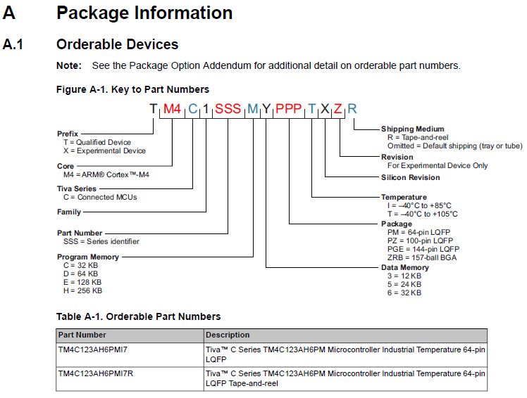
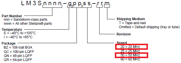
Is there any document, which describes differences between LM3S818-IQN20-B0P and LM3S818-IQN50-C2?

The reason of this question is next:

there is a development kit for motor control - RDK-ACIM  ,
which is based on LM3S818-IQN20-B0 device on the main board.
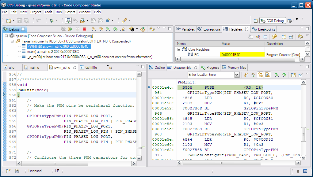
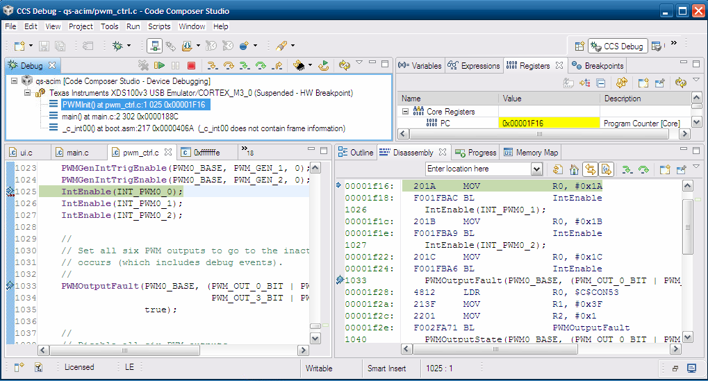
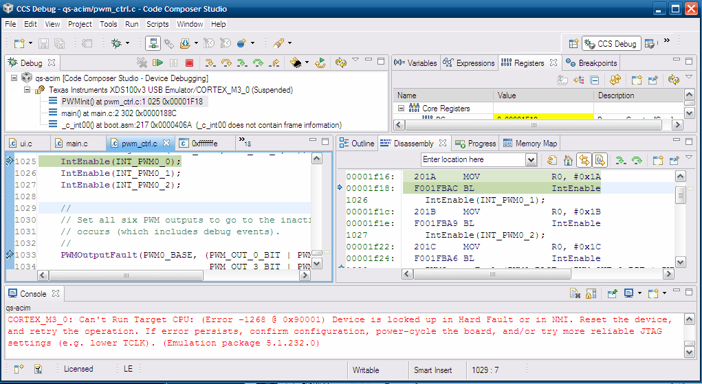
This design was repeated for educational purposes on LM3S818-IQN50-C2. But software doesn't work on this design. Furthermore, debugging in CodeComposerStudio 5.5 is very complicated because of huge amount of "hangs out".

So, which changes shoul be done to make RDK-ACIM software to work on LM3S818-IQN50-C2?

Thanks for help ahead of time.

  • Feel your pain - have you reviewed your MCU manual - especially the "Package Information" usually @ the rear of the manual?  Here's such from a more current device:

    Now this format is not for your device - but shows what you need to acquire.

    We past used LM3S811 - it was far more popular/adopted than 818 - and past (detailed) MCU Manuals may have the information you seek w/in.  See if you have or can find one - we may have such in storage - if you're "dead in the water" perhaps I can "dig" this up this weekend...

  • Vyacheslav Prokopiy said:
    ...design was repeated...LM3S818-IQN50-C2..software doesn't work!

    "Doesn't work" surely clear/known to you - not so much to your hapless, remote "helpers."  We need (some) detail.

    Surely a small test program runs/works - does it not?  And - as you gradually bring up/exercise peripherals - do they perform to expectation? 

    C2 suffix indicates newer device than B0 - that's in your favor.

    Minus the factory response - and my "find" of past manual - my guess is that "20 vs. 50" may be device maximum System clock.  (that's an ESWAG - "educated, scientific wild *** guess...")  (you'd expect more - fast & free?)

  • cb1,  thank you for this advice. I was familiar with the next information before I asked my question.

    But it really confused me, because according to this we have 20 MHz maximum speed for LM3S818-IQN20-B0P, which is used on evaluation board from vendor. But...

    If we look into the source code for evaluation board with this device, we can find the string:

    //
    // Configure the processor to run at 50 MHz.
    //
    SysCtlClockSet(SYSCTL_SYSDIV_4 | SYSCTL_USE_PLL | SYSCTL_OSC_MAIN | SYSCTL_XTAL_6MHZ);

    So, to get the system clock we use main oscillator with 6MHz crystal to drive PLL. Then divide PLL's output by 4 to get 50MHz. But how can we get 50 MHz on 20MHz device???

    I can show the place, where my step-by-step debugging on LM3S818-IQN50-C2  crashes at the string:

        IntEnable(INT_PWM0_0);

    And after this string debbuger can't run the programm any more. I will show you screen shots with additional information later.

  • Some additional describing of debug process.

    1. Go to the PWMInit function with breakpoint. Go into PWMInit function with yellow arrow "Step Into"

    2. Go to the IntEnable function in the body of PWMInit function with breakpoint

    3. If I try to do "Step Over" or "Resume" to go to the next BP - receive the error:

    4. But if I try to go from IntEnable function to PWMOutputFault with green arrow "Assembly Step Into" it works and achieves the second function.

    I use CCS 5.5 and XDS100v2 as a debugger. I will appreciate for any useful comment.

  • Vyacheslav Prokopiy said:
    I will appreciate for any useful comment.

    Always dangerous for responders when posters' limit comments to, "useful." 

    Your initial writing did not convey your earlier "find" of part marking detail - that would have proved, "useful!"

    Usually the hard fault you list springs from failure to enable that specific, MCU peripheral, prior to its access.  Yet - as yours is (one hopes) essentially unmodified RDK code - hard to imagine that's the case.  Begs the question - have you modified the RDK code - specifically w/in the PWM0 area?

    Suggest that you (temporarily) dial the System Clock down from 50MHz to 20MHz - just as a test to see if that impacts your PWM0 hard fault.  I can report that we used LM3S16xx (several K) as BLDC Motor controller - with very good success - at full 50MHz system clock. 

    As always - should that original board (i.e. your "Golden Board") still be present - I'd load your most recent code and see if "really" the issue is chip difference.  Facts in evidence point to your newer MCU being better equipped (not worse) for your target application...

  • The RDK code was changed, but not within the PWM0 area. Some changes was done in buttons control statemachine. Furthermore, this new code works on original RDK-ACIM kit. But doesn't work on my board.
    And what about code execution in debug mode. Don't you find it strange, that the same code can run in asm step-mode and can't run in common mode? Or is it my fault and I do something wrong?

  • Vyacheslav Prokopiy said:
    this new code works on original RDK-ACIM kit...doesn't on my (new) board.

    It remains unclear if you still have your "original" (i.e. Golden board) and if you've then (really) loaded that exact, "new code" into the original board - and then run identical tests.  That's the best means my tech group employs to perform a valid, MCU-MCU comparision.  ("close" to the same is not, "exact")  Very often we find that clients have changed code (at some place, some time) and that not all such changes have been recorded or logged.

    Our group provides ARM MCU designs from many vendors.  (hard to imagine that one vendor will always have, "best/brightest" MCU, w/needed features, speeds, prices & availability)  Thus we've never used CCS - unlikely we ever will.  Free versions of IAR/Keil may be downloaded - both are more mature and many find these superior...  We've never noted the, "Run in asm step mode" but fail in "common mode" that you report. (perhaps a CCS hidden "feature")

    The hard fault w/in PWM0 code remains a major concern - again I'd insure that the peripheral is properly enabled and that all interrupt handlers are properly listed w/in start-up file and correct in their coding w/in your (we suspect) PWM control file.

    [added 09:22 CST] Dawns that if the original MCU ran @ 20MHz - and the new @ 50MHz - and if you immediately follow the "SysCtlPeripheralEnable(PWM0)" (check that - it's from my memory) with a call to PWM0 - the increased MCU System Clock may yield that fault on your new (i.e. faster) board!  And - when you "escape" to single-step ASM - delay is naturally inserted - eliminating the incomplete enabling of PWM0 and thus your hard fault...  Manual states that you should insert delay after "PeripheralEnable()" and before calling that peripheral.  (hallowed, past vendor listed such delay in number of MCU clocks - which should avoid any system clock sensitivity - yet we have seen cases (especially w/older parts (LM3S)) where added delays cured similar issues...)

  • Hi everyone!

    Alright, after some investigations was done, the following was established:

    1. There is a mistake in RDK-ACIM documentation. Actually on board LM3S818-IQN50-C2DD is present, not LM3S818-IQN20-B0 like it's specified in documentation.
    2. Design was repeated on microcontroller LM3S818I-QN50-C2SD. The same programm works fine on board from manufacturer (i.e. "golden" board) with LM3S818-IQN50-C2DD and doesn't work on customer's board with LM3S818-IQN50-C2SD. If be acicurate - Hard Fault or NMI appears on new design when software tries to enable a PWM interrupt.

    3. After several efforts to fix software for customer's board with LM3S818-IQN50-C2SD, the next desigion was made: solder out LM3S818-IQN50-C2DD from original board and put it on customer's board instead of LM3S818I-QN50-C2SD. This action gave good results - customer's board began to work. So we can make a conclusion, that customer's hardware design was made good, without lacks.

    4. The last mismatch, that can be source of problem, is the last characters in controllers names: SD and DD.

    Maybe, someone is familiar with this issue and can help me on this? What else have I to check to manage with this problem?

  • cb1_mobile said:
    when you "escape" to single-step ASM - delay is naturally inserted - eliminating the incomplete enabling of PWM0 and thus your hard fault... 

    While your new writing is of interest it fails to verify your test/verify of the suggestion (quoted) above.  Earlier you listed your issue as "hard fault" when making a call to PWM0 peripheral.  Adding suitable delays prior to accessing any peripheral is a proven means to reduce (often eliminate) such occurrence.

    You may also wish to "exercise" that PWM peripheral in a more general manner to establish that it can be made to work and is properly identified w/in the MCU manual...  (i.e. calls to improperly identified (i.e. non-existent) peripherals are not usually successful)

  • 1. About delays in asm mode

    For me it's absolutely not clear: how can it be possible, that on the same revision of silicon (C2) we get the fault on one chip, and dont get on another. Could you explain a little bit more how can it be possible? I believe, delays should be exactly the same on both chips, because they have the same revision. Am I wrong?


    2. About existing peripherial

    Again there is a same question. If we use the same core, I mean the same silicon. Two chips have C2 revision, and the same datasheet, hence the same peripherial (also PWM module). How can it be, that in exactly the same silicon peripherial can be absent?

  • Feel your pain - I'm about as much in the dark of the "real" how/why as are you.

    Yet - you resist the twice (now) repeated suggestion to dial in delay after enabling your "fault inducing" PWM peripheral.  Should not your first (real) goal be to get the system to work - so that you may complete your (assumed) order?  (as a small biz owner - for some time - that's always our objective)

    Recall that these parts were prematurely, "retired" - and while vendor has never explained/justified - one assumes that they had (some) reason.  Other (more productive) windmills await your charge - I'd "pass" on how/why (this NRND MCU obsession) and instead attempt any/all "reasonable" fixes.  While not to your liking - believe my approach far better addresses your, "reality."

    If you have any purchasing volume - local Sales office may be able to assist.  (though support for these NRND MCUs is not "top cabin" priority...)  I have tried - your cry here has not, "pulled in too many..."

  • So, you recommend to add some delay before call   IntEnable(INT_PWM0_0);. Do I understand correctly?

    I'll try this, but in source code we have   SysCtlPeripheralSleepEnable(SYSCTL_PERIPH_PWM0); at the beginning of main() and then, much later we enable this interrupt. So, when interrupt is enabling, PWM module should be already enabled.

    But anyway thank you for advice very much. I'll write about results later.

  • ARM Peripherals (here/elsewhere) most always must be clocked/enabled prior to their access.  I don't believe that your call to "sleep enable" is full/proper for that purpose.  If you wish - you may reveal the source for "sleep enable" and see if it fully/completely duplicates the actions taken by SysCtlPeripheralEnable().  (I don't believe that to be the case.)

    Classically there should be some delay inserted between, "SysCtlPeripheralEnable(SYSCTL_PERIPH_PWM0)" and any subsequent access of that PWM0 peripheral.  As you have already stated that your existing code - minus any delay (as revealed by your code listing) - immediately lands you into a fault routine - this seems like a most obvious, "first order attempt" to correct such fault.