A related question is a question created from another question. When the related question is created, it will be automatically linked to the original question.
If you have a related question, please click the "Ask a related question" button in the top right corner. The newly created question will be automatically linked to this question.
I would like to interface 4 Temperature Sensor to the TM4C1294 Launchpad , unfortunately Tivaware does not contains any ADC examples so please guide me to start working on it.
I would like to interface 4 Temperature Sensor to the TM4C1294 Launchpad
What temperature sensors do you want to interface to TM4C1294 Launchpad? Provide a link to those Temperature Sensors.
asokfair said:
unfortunately Tivaware does not contains any ADC examples so please guide me to start working on it.
See, ADC examples at this Tivaware folder location, "\\examples\peripherals\adc". There are also ADC code example at Tivaware Peripheral Library User's Guide.\
I have here how i create a project. And also how i use a generic start project to create new projects by importing the generic one. (Remember this is how i create it and it works, i can be not the best)
// Choose Sequencer 2 and set it at the highest Priority. ADCSequenceConfigure(ADC0_BASE, 0, ADC_TRIGGER_ALWAYS, 0);
// Choose Step 0 in Sequencer 2 as Data Buffer, set it as last Step and enable Interrupts ADCSequenceStepConfigure(ADC0_BASE,0,0, ADC_CTL_CH0); ADCSequenceStepConfigure(ADC0_BASE,0,1, ADC_CTL_CH1 | ADC_CTL_IE | ADC_CTL_END);
ADCSequenceEnable(ADC0_BASE, 0);
now i want to add three more channels. (PE0,PE1,PE2) how do i can change this above code?
When the interrupt comes or the Status Polling indicates that conversion is complete then you have to read 4 units of ADC Data. The order of the data will be channel0,1,2 and 3
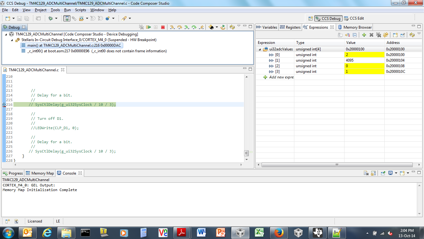
when i modified the code like above you mentioned , its reading only the CH1 values , other 3 channel values not updating. pls refer the attached picture.
My ADC Reading function is given below,
uint32_t WaitAndReadADC(uint32_t *adcValues) {
ADCProcessorTrigger(ADC0_BASE,0); // Wait until the sample sequence has completed.
while(!ADCIntStatus(ADC0_BASE, 0, false)) { } // Read the value from the ADC.
What you have done is correct and needs no modification. Did you try changing the voltage value on the 4 pins and then check if the values read in the array after ADC conversion do change?
I am changing the voltage values , 0 and 3.3v in all PE0,PE1,PE2 and PE3 pins but it changes the value in adcValues[0] none of other are not changing the value
my doubt is this following ADC Read Call with 0 is correct for reading CH1 ,CH2,CH3 values?
ADCSequenceDataGet(ADC0_BASE, 0, adcValues)
because in qs_iot example project , the internal temperature is reading by using sequence number 3
also it has different configuration like ADC_TRIGGER_PROCESSOR is used instead of the Always Trigger
Yes if i use only one Channel , the working perfectly but when i want use multi channel like CH0 (temp1), CH1(temp2), CH2(temp3) and CH3(temp4) its not working.
I want to read the voltage across the 4 Channels pins (PE0,PE1,PE2,PE3)
//*****************************************************************************
//
// hello.c - Simple hello world example.
//
// Copyright (c) 2013-2014 Texas Instruments Incorporated.  All rights reserved.
// Software License Agreement
//
// Texas Instruments (TI) is supplying this software for use solely and
// exclusively on TI's microcontroller products. The software is owned by
// TI and/or its suppliers, and is protected under applicable copyright
// laws. You may not combine this software with "viral" open-source
// software in order to form a larger program.
//
// THIS SOFTWARE IS PROVIDED "AS IS" AND WITH ALL FAULTS.
// NO WARRANTIES, WHETHER EXPRESS, IMPLIED OR STATUTORY, INCLUDING, BUT
// NOT LIMITED TO, IMPLIED WARRANTIES OF MERCHANTABILITY AND FITNESS FOR
// A PARTICULAR PURPOSE APPLY TO THIS SOFTWARE. TI SHALL NOT, UNDER ANY
// CIRCUMSTANCES, BE LIABLE FOR SPECIAL, INCIDENTAL, OR CONSEQUENTIAL
// DAMAGES, FOR ANY REASON WHATSOEVER.
//
// This is part of revision 2.1.0.12573 of the EK-TM4C1294XL Firmware Package.
//
//*****************************************************************************

#include <stdint.h>
#include <stdbool.h>
#include "inc/hw_memmap.h"
#include "inc/hw_types.h"
#include "inc/hw_adc.h"
#include "inc/hw_timer.h"
#include "driverlib/gpio.h"
#include "drivers/pinout.h"
#include "driverlib/pin_map.h"
#include "driverlib/rom.h"
#include "driverlib/rom_map.h"
#include "driverlib/sysctl.h"
#include "driverlib/adc.h"
#include "driverlib/timer.h"
#include "driverlib/uart.h"
#include "utils/uartstdio.h"

//*****************************************************************************
//
//! \addtogroup example_list
//! <h1>Hello World (hello)</h1>
//!
//! A very simple ``hello world'' example.  It simply displays ``Hello World!''
//! on the UART and is a starting point for more complicated applications.
//!
//! Open a terminal with 115,200 8-N-1 to see the output for this demo.
//
//*****************************************************************************
uint32_t ui32adcValues[4],ui32Count,ui32adc0Values[1],ui32adc1Values[1],ui32adc2Values[1],ui32adc3Values[1];


//*****************************************************************************
//
// System clock rate in Hz.
//
//*****************************************************************************
uint32_t g_ui32SysClock;

//*****************************************************************************
//
// The error routine that is called if the driver library encounters an error.
//
//*****************************************************************************
#ifdef DEBUG
void
__error__(char *pcFilename, uint32_t ui32Line)
{
}
#endif

//*****************************************************************************
//
// Configure the UART and its pins.  This must be called before UARTprintf().
//
//*****************************************************************************
void
ConfigureADC(void)
{


		SysCtlPeripheralReset(SYSCTL_PERIPH_GPIOE);
		SysCtlPeripheralEnable(SYSCTL_PERIPH_GPIOE);
		SysCtlPeripheralReset(SYSCTL_PERIPH_ADC0);
		SysCtlPeripheralEnable(SYSCTL_PERIPH_ADC0);
		SysCtlDelay(10);

	    GPIOPinTypeADC(GPIO_PORTE_BASE, GPIO_PIN_3 | GPIO_PIN_2 | GPIO_PIN_1 | GPIO_PIN_0 );

	    ADCClockConfigSet(ADC0_BASE, ADC_CLOCK_SRC_PLL | ADC_CLOCK_RATE_EIGHTH, 30);

	    	// Choose Sequencer 2 and set it at the highest Priority.
    	ADCSequenceConfigure(ADC0_BASE, 0, ADC_TRIGGER_ALWAYS,  0);

    	ADCSequenceConfigure(ADC0_BASE, 1, ADC_TRIGGER_ALWAYS,  0);

    	ADCSequenceConfigure(ADC0_BASE, 2, ADC_TRIGGER_ALWAYS,  0);

    	ADCSequenceConfigure(ADC0_BASE, 3, ADC_TRIGGER_ALWAYS,  0);

	    	// Choose Step 0 in Sequencer 2 as Data Buffer, set it as last Step and enable Interrupts


    	 ADCSequenceStepConfigure(ADC0_BASE,0,0, ADC_CTL_CH0);
    	 ADCSequenceStepConfigure(ADC0_BASE,0,1, ADC_CTL_CH1);

    	 ADCSequenceStepConfigure(ADC0_BASE,0,2, ADC_CTL_CH2);

    	 ADCSequenceStepConfigure(ADC0_BASE,0,3, ADC_CTL_CH3 | ADC_CTL_IE | ADC_CTL_END);


    	ADCSequenceEnable(ADC0_BASE, 0);
    	ADCSequenceEnable(ADC0_BASE, 1);
    	ADCSequenceEnable(ADC0_BASE, 2);
    	ADCSequenceEnable(ADC0_BASE, 3);


}


uint32_t
WaitAndReadADC(uint32_t *adcValues)
{

	ADCProcessorTrigger(ADC0_BASE,0);
    // Wait until the sample sequence has completed.

    while(!ADCIntStatus(ADC0_BASE, 0, false)) { }
    // Read the value from the ADC.


    return(ADCSequenceDataGet(ADC0_BASE, 0, adcValues));
}


uint32_t
WaitAndReadADC1(uint32_t *adcValues)
{

	ADCProcessorTrigger(ADC0_BASE,1);
    // Wait until the sample sequence has completed.

    while(!ADCIntStatus(ADC0_BASE, 1, false)) { }
    // Read the value from the ADC.


    return(ADCSequenceDataGet(ADC0_BASE, 1, adcValues));
}

uint32_t
WaitAndReadADC2(uint32_t *adcValues)
{

	ADCProcessorTrigger(ADC0_BASE,2);
    // Wait until the sample sequence has completed.

    while(!ADCIntStatus(ADC0_BASE, 2, false)) { }
    // Read the value from the ADC.


    return(ADCSequenceDataGet(ADC0_BASE, 2, adcValues));
}

uint32_t
WaitAndReadADC3(uint32_t *adcValues)
{

	ADCProcessorTrigger(ADC0_BASE,3);
    // Wait until the sample sequence has completed.

    while(!ADCIntStatus(ADC0_BASE, 3, false)) { }
    // Read the value from the ADC.


    return(ADCSequenceDataGet(ADC0_BASE, 3, adcValues));
}


//*****************************************************************************
//
// Print "Hello World!" to the UART on the Intelligent UART Module.
//
//*****************************************************************************
int
main(void)
{

    //
    // Run from the PLL at 120 MHz.
    //
    g_ui32SysClock = MAP_SysCtlClockFreqSet((SYSCTL_XTAL_25MHZ |
                SYSCTL_OSC_MAIN | SYSCTL_USE_PLL |
                SYSCTL_CFG_VCO_480), 120000000);

    //
    // Configure the device pins.
    //
    PinoutSet(false, false);

    //
    // Enable the GPIO pins for the LED D1 (PN1).
    //
    ROM_GPIOPinTypeGPIOOutput(GPIO_PORTN_BASE, GPIO_PIN_1);

    //
    // Initialize the UART.
    //
    ConfigureADC();

    //
    // Hello!
    //


    //
    // We are finished.  Hang around flashing D1.
    //
    while(1)
    {


        //
        // Turn on D1.
        //
        LEDWrite(CLP_D1, 1);
     	//ui32Count = WaitAndReadADC0(ui32adc0Values);
     	//ui32Count = WaitAndReadADC1(ui32adc1Values);
     	//ui32Count = WaitAndReadADC2(ui32adc2Values);
     	ui32Count = WaitAndReadADC(ui32adcValues);


        //
        // Delay for a bit.
        //
       // SysCtlDelay(g_ui32SysClock / 10 / 3);

        //
        // Turn off D1.
        //
        LEDWrite(CLP_D1, 0);

        //
        // Delay for a bit.
        //
       // SysCtlDelay(g_ui32SysClock / 10 / 3);
    }
}
I tested the code on my DK-TM4C129 by connecting one-by-one PE0, PE1, PE2 and PE3 to 3.3V and remaining to GND.
Also the ALWAYS_TRIGGER and the PROCESSOR_TRIGGER don't go hand in hand since the Always trigger will cause a trigger to occur all the time and when you use the variable window the data will shift as the sampler is working but the CCS has halted the CPU
//*****************************************************************************
//
// hello.c - Simple hello world example.
//
// Copyright (c) 2013-2014 Texas Instruments Incorporated.  All rights reserved.
// Software License Agreement
//
// Texas Instruments (TI) is supplying this software for use solely and
// exclusively on TI's microcontroller products. The software is owned by
// TI and/or its suppliers, and is protected under applicable copyright
// laws. You may not combine this software with "viral" open-source
// software in order to form a larger program.
//
// THIS SOFTWARE IS PROVIDED "AS IS" AND WITH ALL FAULTS.
// NO WARRANTIES, WHETHER EXPRESS, IMPLIED OR STATUTORY, INCLUDING, BUT
// NOT LIMITED TO, IMPLIED WARRANTIES OF MERCHANTABILITY AND FITNESS FOR
// A PARTICULAR PURPOSE APPLY TO THIS SOFTWARE. TI SHALL NOT, UNDER ANY
// CIRCUMSTANCES, BE LIABLE FOR SPECIAL, INCIDENTAL, OR CONSEQUENTIAL
// DAMAGES, FOR ANY REASON WHATSOEVER.
//
// This is part of revision 2.1.0.12573 of the EK-TM4C1294XL Firmware Package.
//
//*****************************************************************************

#include <stdint.h>
#include <stdbool.h>
#include "inc/hw_memmap.h"
#include "inc/hw_types.h"
#include "inc/hw_adc.h"
#include "inc/hw_timer.h"
#include "driverlib/gpio.h"
#include "drivers/pinout.h"
#include "driverlib/pin_map.h"
#include "driverlib/rom.h"
#include "driverlib/rom_map.h"
#include "driverlib/sysctl.h"
#include "driverlib/adc.h"
#include "driverlib/timer.h"
#include "driverlib/uart.h"
#include "utils/uartstdio.h"

//*****************************************************************************
//
//! \addtogroup example_list
//! <h1>Hello World (hello)</h1>
//!
//! A very simple ``hello world'' example.  It simply displays ``Hello World!''
//! on the UART and is a starting point for more complicated applications.
//!
//! Open a terminal with 115,200 8-N-1 to see the output for this demo.
//
//*****************************************************************************
uint32_t ui32adcValues[4],ui32Count,ui32adc0Values[1],ui32adc1Values[1],ui32adc2Values[1],ui32adc3Values[1];


//*****************************************************************************
//
// System clock rate in Hz.
//
//*****************************************************************************
uint32_t g_ui32SysClock;

//*****************************************************************************
//
// The error routine that is called if the driver library encounters an error.
//
//*****************************************************************************
#ifdef DEBUG
void
__error__(char *pcFilename, uint32_t ui32Line)
{
}
#endif

//*****************************************************************************
//
// Configure the UART and its pins.  This must be called before UARTprintf().
//
//*****************************************************************************
void
ConfigureADC(void)
{


		SysCtlPeripheralReset(SYSCTL_PERIPH_GPIOE);
		SysCtlPeripheralEnable(SYSCTL_PERIPH_GPIOE);
		SysCtlPeripheralReset(SYSCTL_PERIPH_ADC0);
		SysCtlPeripheralEnable(SYSCTL_PERIPH_ADC0);
		SysCtlDelay(10);

	    GPIOPinTypeADC(GPIO_PORTE_BASE, GPIO_PIN_3 | GPIO_PIN_2 | GPIO_PIN_1 | GPIO_PIN_0 );

	    ADCClockConfigSet(ADC0_BASE, ADC_CLOCK_SRC_PLL | ADC_CLOCK_RATE_EIGHTH, 30);

   	ADCSequenceStepConfigure(ADC0_BASE,0,0, ADC_CTL_CH0);
   	ADCSequenceStepConfigure(ADC0_BASE,0,1, ADC_CTL_CH1);
   	ADCSequenceStepConfigure(ADC0_BASE,0,2, ADC_CTL_CH2);
   	ADCSequenceStepConfigure(ADC0_BASE,0,3, ADC_CTL_CH3 | ADC_CTL_IE | ADC_CTL_END);

   	ADCSequenceEnable(ADC0_BASE, 0);
   	ADCSequenceEnable(ADC0_BASE, 1);
   	ADCSequenceEnable(ADC0_BASE, 2);
   	ADCSequenceEnable(ADC0_BASE, 3);
}


uint32_t
WaitAndReadADC(uint32_t *adcValues)
{

	ADCProcessorTrigger(ADC0_BASE,0);
    // Wait until the sample sequence has completed.

    while(!ADCIntStatus(ADC0_BASE, 0, false)) { }
    // Read the value from the ADC.


    return(ADCSequenceDataGet(ADC0_BASE, 0, adcValues));
}


uint32_t
WaitAndReadADC1(uint32_t *adcValues)
{

	ADCProcessorTrigger(ADC0_BASE,1);
    // Wait until the sample sequence has completed.

    while(!ADCIntStatus(ADC0_BASE, 1, false)) { }
    // Read the value from the ADC.


    return(ADCSequenceDataGet(ADC0_BASE, 1, adcValues));
}

uint32_t
WaitAndReadADC2(uint32_t *adcValues)
{

	ADCProcessorTrigger(ADC0_BASE,2);
    // Wait until the sample sequence has completed.

    while(!ADCIntStatus(ADC0_BASE, 2, false)) { }
    // Read the value from the ADC.


    return(ADCSequenceDataGet(ADC0_BASE, 2, adcValues));
}

uint32_t
WaitAndReadADC3(uint32_t *adcValues)
{

	ADCProcessorTrigger(ADC0_BASE,3);
    // Wait until the sample sequence has completed.

    while(!ADCIntStatus(ADC0_BASE, 3, false)) { }
    // Read the value from the ADC.


    return(ADCSequenceDataGet(ADC0_BASE, 3, adcValues));
}


//*****************************************************************************
//
// Print "Hello World!" to the UART on the Intelligent UART Module.
//
//*****************************************************************************
int
main(void)
{

    //
    // Run from the PLL at 120 MHz.
    //
    g_ui32SysClock = SysCtlClockFreqSet((SYSCTL_XTAL_25MHZ |
                SYSCTL_OSC_MAIN | SYSCTL_USE_PLL |
                SYSCTL_CFG_VCO_480), 120000000);

    //
    // Configure the device pins.
    //
    PinoutSet();

    //
    // Enable the GPIO pins for the LED D1 (PN1).
    //
    ROM_GPIOPinTypeGPIOOutput(GPIO_PORTN_BASE, GPIO_PIN_1);

    //
    // Initialize the UART.
    //
    ConfigureADC();

    //
    // Hello!
    //


    //
    // We are finished.  Hang around flashing D1.
    //
    while(1)
    {


        //
        // Turn on D1.
        //
        //LEDWrite(CLP_D1, 1);
     	//ui32Count = WaitAndReadADC0(ui32adc0Values);
     	//ui32Count = WaitAndReadADC1(ui32adc1Values);
     	//ui32Count = WaitAndReadADC2(ui32adc2Values);
     	ui32Count = WaitAndReadADC(ui32adcValues);


        //
        // Delay for a bit.
        //
       // SysCtlDelay(g_ui32SysClock / 10 / 3);

        //
        // Turn off D1.
        //
        //LEDWrite(CLP_D1, 0);

        //
        // Delay for a bit.
        //
       // SysCtlDelay(g_ui32SysClock / 10 / 3);
    }
}
Attached is the snapshot of the Memory Window and it reads fine.
Please note that the Priority of the Sequencers cannot be the same. They are graded. So in case you put all of them to the same priority the default order of 0.1.2.3 will happen.