This thread has been locked.
If you have a related question, please click the "Ask a related question" button in the top right corner. The newly created question will be automatically linked to this question.
Hi,
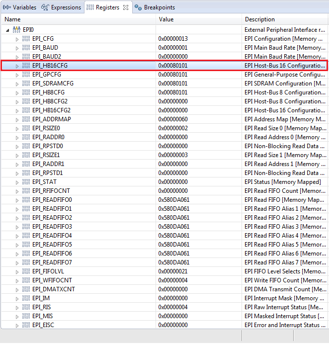
I would like to know if its possible to limit the stall count of the EPI HB16 to a few clock cycles if iRDY is not asserted.
Currently, it seems like the Cortex is waiting indefinitely for the iRDY signal and thus locking up CPU.
In my case this means a complete system failure if one of the chips attached to the Cortex/EPI interface fails.
The EPIConfigHB16TimingSet doesn't do the job
EPIConfigHB16TimingSet(EPI0_BASE,
EPI_HB16_IN_READY_DELAY_1 | //sets the stall on input ready (EPIS032)
//to start 1 EPI clock after signaled
EPI_HB16_WRWAIT_MINUS_ENABLE | //enables a 1 EPI clock write wait state reduction
EPI_HB16_RDWAIT_MINUS_ENABLE); //enables a 1 EPI clock read wait state reduction
Khaled.
Sorry about that. It was more of a general HB16 configuration question. I"m attaching for the configuration file.
Khaled.
int main(void) { //desired system frequency gSysCtlClock = SysCtlClockFreqSet( SYSCTL_USE_PLL | SYSCTL_OSC_MAIN | SYSCTL_XTAL_25MHZ | SYSCTL_CFG_VCO_480, 120000000); SysCtlPeripheralEnable(SYSCTL_PERIPH_EPI0); SysCtlPeripheralReset(SYSCTL_PERIPH_EPI0); SysCtlPeripheralEnable(SYSCTL_PERIPH_GPIOA); SysCtlPeripheralReset(SYSCTL_PERIPH_GPIOA); SysCtlPeripheralEnable(SYSCTL_PERIPH_GPIOB); SysCtlPeripheralReset(SYSCTL_PERIPH_GPIOB); SysCtlPeripheralEnable(SYSCTL_PERIPH_GPIOC); SysCtlPeripheralReset(SYSCTL_PERIPH_GPIOC); SysCtlPeripheralEnable(SYSCTL_PERIPH_GPIOD); SysCtlPeripheralReset(SYSCTL_PERIPH_GPIOD); SysCtlPeripheralEnable(SYSCTL_PERIPH_GPIOE); SysCtlPeripheralReset(SYSCTL_PERIPH_GPIOE); SysCtlPeripheralEnable(SYSCTL_PERIPH_GPIOF); SysCtlPeripheralReset(SYSCTL_PERIPH_GPIOF); SysCtlPeripheralEnable(SYSCTL_PERIPH_GPIOG); SysCtlPeripheralReset(SYSCTL_PERIPH_GPIOG); SysCtlPeripheralEnable(SYSCTL_PERIPH_GPIOH); SysCtlPeripheralReset(SYSCTL_PERIPH_GPIOH); SysCtlPeripheralEnable(SYSCTL_PERIPH_GPIOJ); SysCtlPeripheralReset(SYSCTL_PERIPH_GPIOJ); SysCtlPeripheralEnable(SYSCTL_PERIPH_GPIOK); SysCtlPeripheralReset(SYSCTL_PERIPH_GPIOK); SysCtlPeripheralEnable(SYSCTL_PERIPH_GPIOL); SysCtlPeripheralReset(SYSCTL_PERIPH_GPIOL); SysCtlPeripheralEnable(SYSCTL_PERIPH_GPIOM); SysCtlPeripheralReset(SYSCTL_PERIPH_GPIOM); SysCtlPeripheralEnable(SYSCTL_PERIPH_GPION); SysCtlPeripheralReset(SYSCTL_PERIPH_GPION); SysCtlPeripheralEnable(SYSCTL_PERIPH_GPIOP); SysCtlPeripheralReset(SYSCTL_PERIPH_GPIOP); SysCtlPeripheralEnable(SYSCTL_PERIPH_GPIOQ); SysCtlPeripheralReset(SYSCTL_PERIPH_GPIOQ); SysCtlPeripheralEnable(SYSCTL_PERIPH_GPIOR); SysCtlPeripheralReset(SYSCTL_PERIPH_GPIOR); SysCtlPeripheralEnable(SYSCTL_PERIPH_GPIOS); SysCtlPeripheralReset(SYSCTL_PERIPH_GPIOS); SysCtlPeripheralEnable(SYSCTL_PERIPH_GPIOT); SysCtlPeripheralReset(SYSCTL_PERIPH_GPIOT); GPIOPinConfigure(GPIO_PK5_EPI0S31); //EPI CLK GPIOPinConfigure(GPIO_PP3_EPI0S30); //EPI ALE/HAS GPIOPinConfigure(GPIO_PP2_EPI0S29); //EPI WR GPIOPinConfigure(GPIO_PB3_EPI0S28); //EPI RD GPIOPinConfigure(GPIO_PK4_EPI0S32); //EPI RDY GPIOPinConfigure(GPIO_PL0_EPI0S16); //EPI A0/HHWIL GPIOPinConfigure(GPIO_PK0_EPI0S0); //EPI D0 GPIOPinConfigure(GPIO_PK1_EPI0S1); //EPI D1 GPIOPinConfigure(GPIO_PK2_EPI0S2); //EPI D2 GPIOPinConfigure(GPIO_PK3_EPI0S3); //EPI D3 GPIOPinConfigure(GPIO_PC7_EPI0S4); //EPI D4 GPIOPinConfigure(GPIO_PC6_EPI0S5); //EPI D5 GPIOPinConfigure(GPIO_PC5_EPI0S6); //EPI D6 GPIOPinConfigure(GPIO_PC4_EPI0S7); //EPI D7 GPIOPinConfigure(GPIO_PA6_EPI0S8); //EPI D8 GPIOPinConfigure(GPIO_PA7_EPI0S9); //EPI D9 GPIOPinConfigure(GPIO_PG1_EPI0S10); //EPI D10 GPIOPinConfigure(GPIO_PG0_EPI0S11); //EPI D11 GPIOPinConfigure(GPIO_PM3_EPI0S12); //EPI D12 GPIOPinConfigure(GPIO_PM2_EPI0S13); //EPI D13 GPIOPinConfigure(GPIO_PM1_EPI0S14); //EPI D14 GPIOPinConfigure(GPIO_PM0_EPI0S15); //EPI D15 GPIOPinTypeEPI(GPIO_PORTK_BASE, GPIO_PIN_0 | //EPI D0 GPIO_PIN_1 | //EPI D1 GPIO_PIN_2 | //EPI D2 GPIO_PIN_3); //EPI D3 GPIOPinTypeEPI(GPIO_PORTC_BASE, GPIO_PIN_7 | //EPI D4 GPIO_PIN_6 | //EPI D5 GPIO_PIN_5 | //EPI D6 GPIO_PIN_4); //EPI D7 GPIOPinTypeEPI(GPIO_PORTA_BASE, GPIO_PIN_6 | //EPI D8 GPIO_PIN_7); //EPI D9 GPIOPinTypeEPI(GPIO_PORTG_BASE, GPIO_PIN_1 | //EPI D10 GPIO_PIN_0); //EPI D11 GPIOPinTypeEPI(GPIO_PORTM_BASE, GPIO_PIN_3 | //EPI D12 GPIO_PIN_2 | //EPI D13 GPIO_PIN_1 | //EPI D14 GPIO_PIN_0); //EPI D15 GPIOPinTypeEPI(GPIO_PORTB_BASE, GPIO_PIN_3); //EPI RD GPIOPinTypeEPI(GPIO_PORTP_BASE, GPIO_PIN_2 | //EPI WR GPIO_PIN_3); //EPI ALE GPIOPinTypeEPI(GPIO_PORTK_BASE, GPIO_PIN_4 | //EPI IRDY GPIO_PIN_5); //EPI CLOCK GPIOPinTypeEPI(GPIO_PORTL_BASE, GPIO_PIN_0); //EPI A0/HHWIL // Set pointer to EPI memory mapped window. g_pusEPIFPGA = (uint16_t *)0xC0000000; //reset the EPI interface EPIModeSet( EPI0_BASE, EPI_MODE_DISABLE); // Set the EPI divider. EPIDividerSet( EPI0_BASE, EPI_DIV_FACTOR_DATA); //enable the EPI interface, and use general purpose mode EPIModeSet( EPI0_BASE, EPI_MODE_HB16); EPIConfigHB16Set( EPI0_BASE, // EPI_HB16_IN_READY_EN | //IRDY enabled EPI_HB16_MODE_ADDEMUX | //sets up data and address as separate EPI_HB16_CSCFG_ALE | //EPIS030 to operate as an address latch (ALE) EPI_HB16_ALE_HIGH | //sets the address latch active high EPI_HB16_WRWAIT_0 | //sets write wait state to 2 EPI clocks. EPI_HB16_RDWAIT_0 , //sets read wait state to 2 EPI clocks. 1); //FIFO mode maximum number of clocks EPIConfigHB16TimingSet(EPI0_BASE, 0 , //specifies the chip select to configure[0-3] EPI_HB16_IN_READY_DELAY_1 | //sets the stall on input ready (EPIS032) //to start 1 EPI clock after signaled EPI_HB16_WRWAIT_MINUS_ENABLE | //enables a 1 EPI clock write wait state reduction EPI_HB16_RDWAIT_MINUS_ENABLE); //enables a 1 EPI clock read wait state reduction //setup the address mapping for low level driver // - EPI_HPI_read( ) // - EPI_HPI_write( ) //Note: for some reason if the Epi Rx FIFO trigger level is more // than 1/8, the FIRST word has always a wrong values. EPIAddressMapSet( EPI0_BASE, EPI_ADDR_PER_BASE_C | EPI_ADDR_PER_SIZE_64KB); EPIFIFOConfig( EPI0_BASE, EPI_FIFO_CONFIG_TX_1_4 | EPI_FIFO_CONFIG_RX_1_8); //configure the EPI Non blocking read EPINonBlockingReadConfigure(EPI0_BASE, 0, EPI_NBCONFIG_SIZE_16, 0); //read from the EPI interface while(1) { g_pusEPIFPGA = (uint16_t *)0xC0000000; for(i = 0; i < 10; i++) { word = (uint32_t) *g_pusEPIFPGA; //read lower 16bits g_pusEPIFPGA++; word |= (uint32_t) *g_pusEPIFPGA << 16; //read upper 16bits g_pusEPIFPGA++; u32DataIn[i] = word; }//for loop }//while(1) }//main
Here is a copy of the initial message and how it was resolved
//------------------------------------ message 1 start ----------------------
Hi,
I can't erase the cortex M4 anymore. I'm using keil uVision Version 5.15.0 and RTX for bios.
I have two TM4C129XNCZAD boards. They used to work fine (erase, program and run) until I changed my program (not sure what I have changed) but from that point on, I'm not able to erase the Cortex and I keep getting the following message:
" Could not stop Cortex-M device! Please check the JTAG cable"
I tried reducing the JTAG clock, no success.
I tried to switch from SW, to JTAG, to SW/SWJ... non worked.
I tried to connect through the USB debugger port (ICDI) still no success.
What else can I try.
Khaled.
//------------------------------------ message 2 start ----------------------
These suggestions are taken from the device's datasheet: www.ti.com/.../tm4c129xnczad.pdf Pg. 225 describes one way to recover a 'locked' microcontroller, if the JTAG/SWD pins were also configured as GPIO pins, by accident. Try these steps. Even if this did not specifically occur, it will still cause a mass erase, which should allow the device to be reprogrammed. Pg. 257 describes the Hardware System Service Request (HSSR). This could be another way to trigger a mass erase, try the steps using _WWORD in the Command Window, if the System Viewer does not provide a way to complete the instructions from SYSCTL => RESC => ...HSSR. Pg. 646 also describes another (probably easier) way to perform a mass erase. Let us know if we can be of further assistance. Erasing the device would at least allow you to program it once more before receiving the "Could not stop Cortex-M device" message, to troubleshoot the cause of the message. Thanks, Zack
//------------------------------------ message 3 start ----------------------
Zack thank you for the additional info. I tried the first approach by switching between JATG and SW using the Keil/uvision/Flash/Debug/setting/Port with no success. I think that I'm doing it wrong. I was not able to try the second and third approach. I don't know how to write to the different registers while the Cortex is down. Do you have a program/executable that I can install that could apply those sequences for me? thanks. Khaled.
//------------------------------------ message 4 start ----------------------
Hello Khaled,
The process described on Pg. 225 is your best option, then. I think switching the ports in the Target Driver Setup for the ULINK2 would complete all the steps (1-3), when the instructions only want you to complete Steps 1 and 2.
There might be an automated way to do this, with LM Flash programmer/utility: www.ti.com/.../lmflashprogrammer Download and install the software, if you do not already have it on your computer. Go to Configuration tab => Select the appropriate interface. Then go to Other Utilities tab => Debug Port Unlock => Select the option that includes the TM4C129 class. Then click "Unlock".
Otherwise, you should find another utility that will allow this group and timing of sequences or write the code to use a serial cable to send these signals (Visual Studio has some pre-built methods to help accomplish this) to the SW/JTAG interface. It would be worth the effort to automate this, because even if you recovered a device, you would want to be able to debug why the SW/JTAG interface was disrupted in the first place, and to quickly unlock the device if the issue reoccurs.
Our tools lack a solution for this type of problem, so I am sorry, but you will have to find some other way to unlock the device, which we cannot really support. In this case, we can only point to where you may find answers.
Good luck! Regards, Zack
//------------------------------------ message 5 start ----------------------
Hi Zack
using the lm flash programmer did the trick :-)
thanks.
Khaled.
//------------------------------------ message end ----------------------
Here is a copy of the EPI registers. Hope its what you are asking for.
Khaled.
Hi Amit,
It seems the snap shot of the registers were not uploaded.
Here they are again.
Khaled.
Amit,
I commented out the iRDY enable command on purpose to get my testing going.
I more or less reached the same conclusion as you: the external device has to assert high the iRDY in order for the Cortex not to stall indefinitely.
My original question still stands: is there is a way to configure the Cortex/Epi interface/iRDY NOT TO STALL the cortex indefinitely?
In my case, if the external device do not assert the iRDY signal, the Cortex dies as well and the entire system is lost!
Khaled.