Other Parts Discussed in Thread: TM4C129XNCZAD, TMS320C6472
Hi,
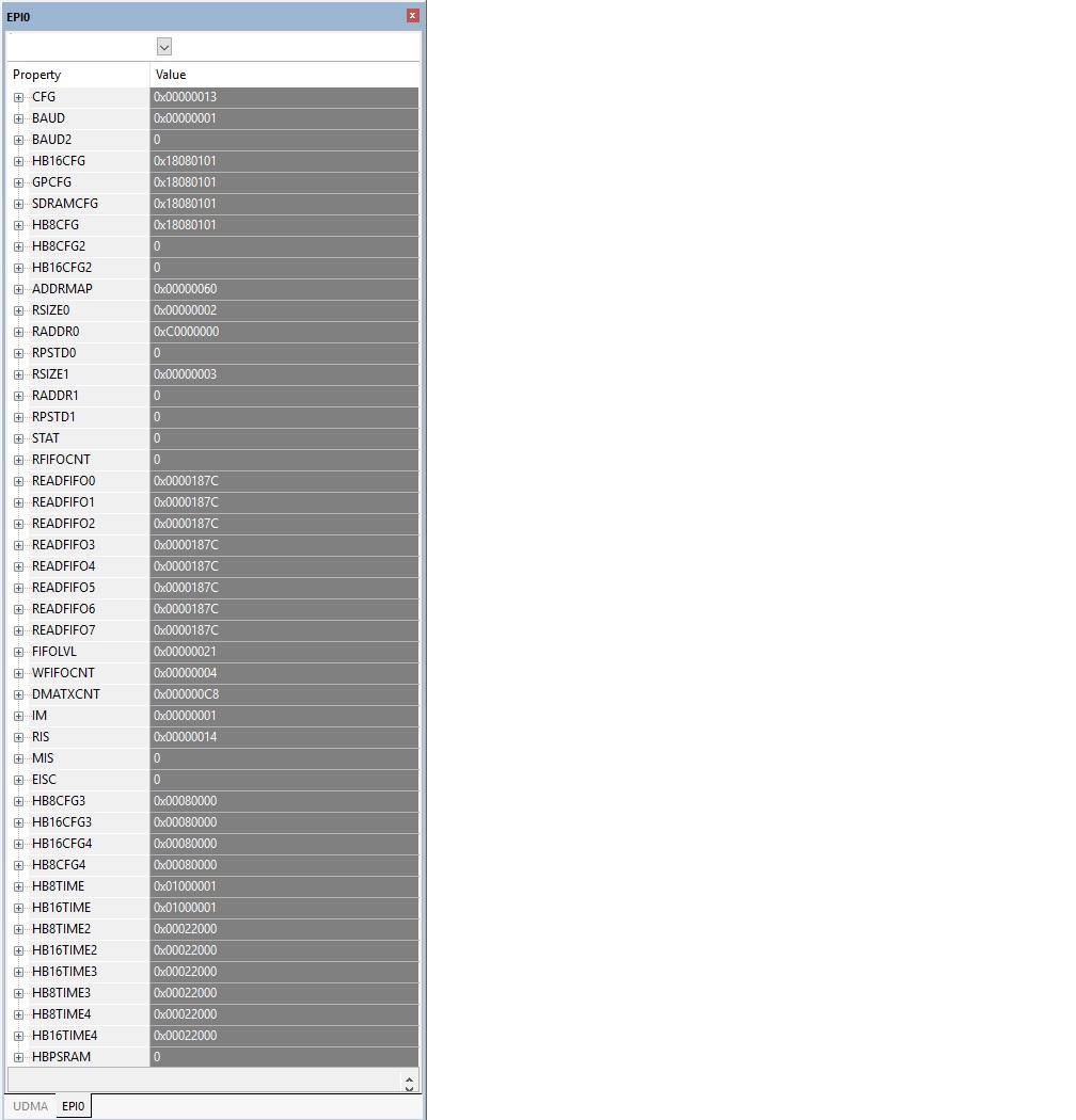
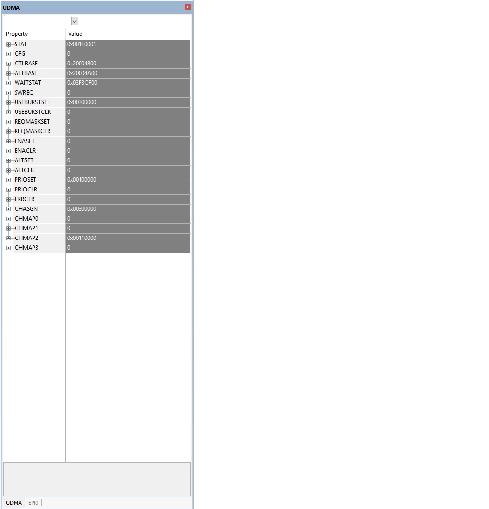
I'm having trouble getting the EPI uDMA write to function properly.
I have EPI write (no uDMA) working, EPI read (no uDMA) working and EPI uDMA read working.
From my tests it seems that the EPI uDMA is not even starting!
Please help.
Khaled.
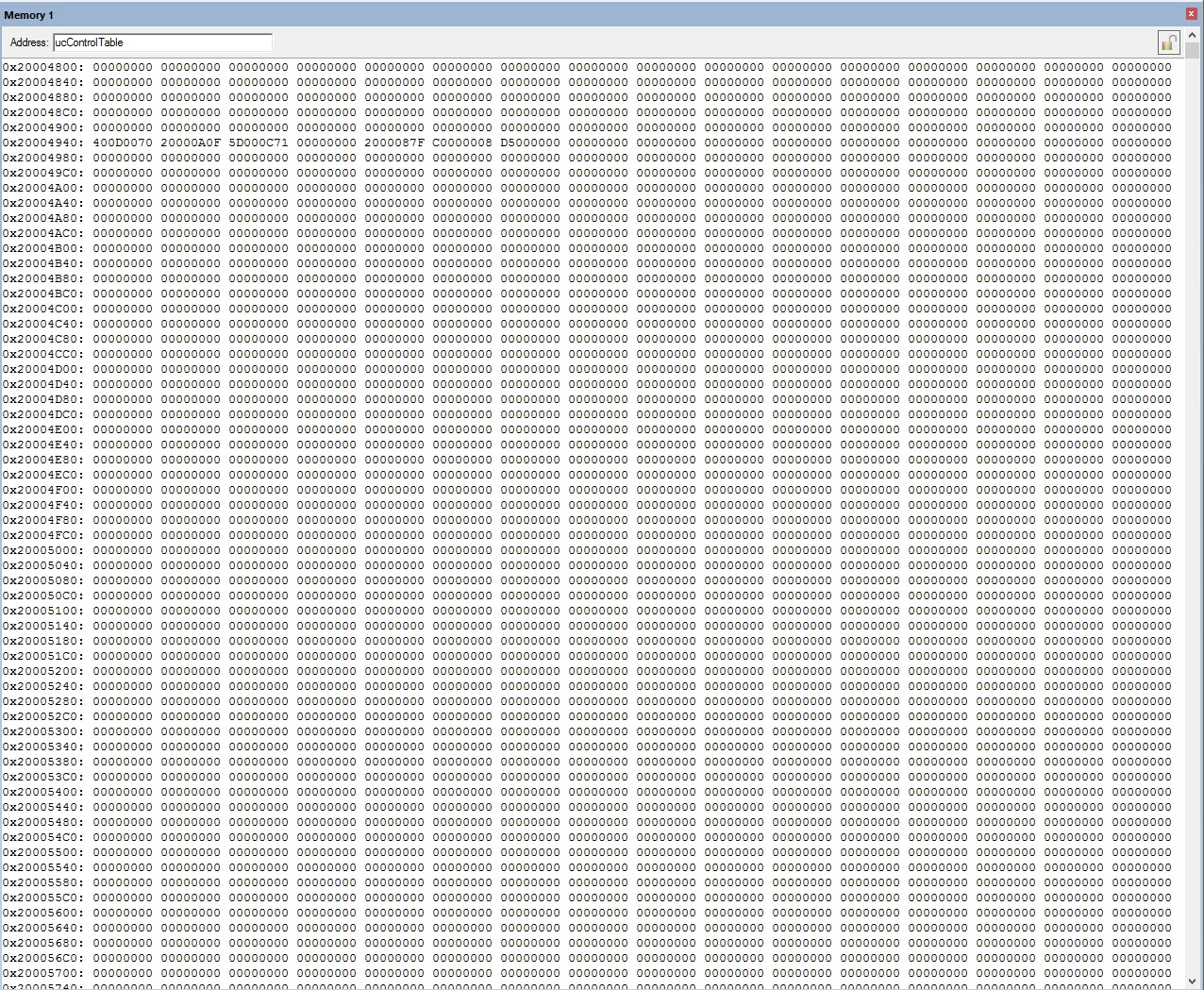
//define the uDMA control table
#if defined(ewarm)
#pragma data_alignment=1024
unsigned char ucControlTable[1024];
#elif defined(ccs)
#pragma DATA_ALIGN(ucControlTable, 1024)
tDMAControlTable ucControlTable[1024];
#else
unsigned char ucControlTable[1024] __attribute__ ((aligned(1024)));
#endif

volatile uint16_t *g_pusEPIFPGA; // Pointer for EPI memory window.

uint32_t u32DataIn[100];
uint32_t u32DataOut[100];
uint32_t numSuccess;
uint32_t numFail;

/**********************************************************************
**********************************************************************/
int main(void) {

	uint16_t i;
	uint32_t status;
	uint16_t errorIndex;


	SystemInit();  					//system setup
	GPIO_Init();   					//setup GPIO
	uDMA_Init();   					//setup the uDMA
	EPI_Init(); 					//setup EPI HPI interface

	//test the access to the DSP/HPI interface
	numFail    = 0; 	numSuccess = 0;
	while(1) {
		//fill with dummy data
		for(i = 0; i < 100; i++) {
			u32DataIn[i]  = i;
			u32DataOut[i] = 0x0BAD0BAD;
		}

		EPI_HPI_write     ( u32DataIn, 100, (uint32_t *) HPI_MEM_DAC_TX_START);
		while((!EPIdone())) {		}	//wait until uDMA is done

		EPI_HPI_read      ((uint32_t *) HPI_MEM_DAC_TX_START, 100, u32DataOut);
		while((!EPIdone())) {		}	//wait until uDMA is done

		//compare
		for(i = 0, errorIndex = 0xFFFF; i < 100; i++) {
			if(u32DataIn[i] != u32DataOut[i]) numFail++;
			else                              numSuccess++;
		}//for all

//		status  = EPI_HPI_uDMA_write( u32DataIn, 100, (uint32_t *) HPI_MEM_DAC_TX_START);
//		while((!EPIdone())) {		}	//wait until uDMA is done

		status &= EPI_HPI_uDMA_read ((uint32_t *) HPI_MEM_DAC_TX_START, 100, u32DataOut);
//		SysCtlDelay(gSysCtlClock * 1e-3);
//		wait for uDMA interrupt
//		wait for uDMA to finish
		while((!EPIdone())) {		}	//wait until uDMA is done

		//compare
		for(i = 0, errorIndex = 0xFFFF; i < 100; i++) {
			if(u32DataIn[i] != u32DataOut[i]) numFail++;
			else                              numSuccess++;
		}//for all
	}//while(1)
}//main

/**********************************************************************
**********************************************************************/
void EPI_Init(void) {

	// Set pointer to EPI memory mapped window.
	g_pusEPIFPGA = (uint16_t *)0xC0000000;

	//reset the EPI interface
	EPIModeSet(			EPI0_BASE,
						EPI_MODE_DISABLE);

	// Set the EPI divider.
	EPIDividerSet(		EPI0_BASE,
						1);

	//enable the EPI interface, and use general purpose mode
	EPIModeSet(			EPI0_BASE,
						EPI_MODE_HB16);
    EPIConfigHB16Set(	EPI0_BASE,
//						EPI_HB16_USE_TXEMPTY          |		//Tx fifo empty enable
//						EPI_HB16_USE_RXFULL           |		//Rx fifo full enable
//						EPI_HB16_BURST_TRAFFIC        | 	//burst mode enabled
						EPI_HB16_IN_READY_EN          |  	//IRDY enabled
						EPI_HB16_IN_READY_EN_INVERTED |		//IRDY polarity inverted
						EPI_HB16_MODE_ADDEMUX         | 	//sets up data and address as separate
						EPI_HB16_CSCFG_ALE            |		//EPIS030 to operate as an address latch (ALE)
						EPI_HB16_ALE_HIGH             |		//sets the address latch active high
						EPI_HB16_WRWAIT_0             |		//sets write wait state to 2 EPI clocks.
						EPI_HB16_RDWAIT_0             , 	//sets read wait state to 2 EPI clocks.
						0xF0);								//FIFO mode	maximum number of clocks
	EPIConfigHB16TimingSet(EPI0_BASE,
						0			,						//specifies the chip select to configure[0-3]
						EPI_HB16_IN_READY_DELAY_1     |   	//sets the stall on input ready (EPIS032)
															//to start 1 EPI clock after signaled
						EPI_HB16_WRWAIT_MINUS_ENABLE  |		//enables a 1 EPI clock write wait state reduction
						EPI_HB16_RDWAIT_MINUS_ENABLE); 		//enables a 1 EPI clock read wait state reduction

	//setup the address mapping for low level driver
	EPIAddressMapSet(	EPI0_BASE,
						EPI_ADDR_PER_BASE_C   |
						EPI_ADDR_PER_SIZE_64KB);
	EPIFIFOConfig(		EPI0_BASE,
						EPI_FIFO_CONFIG_TX_1_4 |
						EPI_FIFO_CONFIG_RX_1_8);

	//configure the EPI Non blocking read
	EPINonBlockingReadConfigure(EPI0_BASE,
								0,
								EPI_NBCONFIG_SIZE_16,
								0);

	//-------------------------------------------------------------
	// Setup the EPI interrupt to service the NBRFIFO and the WFIFO
	// When the NBRFIFO is full, or the WFIFO is empty generate an
	// interrupt or trigger a uDMA transfer to service the buffer
	//-------------------------------------------------------------
	//clear the FIFO interrupt triggers
	EPIIntDisable(   EPI0_BASE, EPI_INT_RXREQ      |
								EPI_INT_TXREQ      |
								EPI_INT_ERR);
	EPIIntErrorClear(EPI0_BASE, EPI_INT_ERR_WTFULL |
								EPI_INT_ERR_RSTALL |
								EPI_INT_ERR_TIMEOUT);

	//setup the interrupt mask for the EPI.
	//Note: interrupt masking has no effect on uDMA, which
	//      operates off the raw source of the read/write
	//      interrupts
	//Note: we dont want to enable the EPI Rx and Tx interrupt,
	//      the EPI fifos will be serviced by the uDMA
    EPIIntEnable(	EPI0_BASE,
// 					EPI_INT_RXREQ       |
// 					EPI_INT_TXREQ       |
//					EPI_INT_DMA_TX_DONE |
//					EPI_INT_DMA_RX_DONE |
					EPI_INT_ERR);

	// Enable the EPI interrupt on the processor (NVIC).
	// Note: even if no EPI interrupt were enabled, the uDMA
	//       controller will generate an interrupt on the EPI
	//       interrupt signal when a uDMA transfer is complete.
	IntEnable(INT_EPI0);

	//-------------------------------------------------------------
	// Configure the uDMA for the EPI read and write
	//-------------------------------------------------------------
	// Put the attributes in a known state for the uDMA EPI channel.
	uDMAChannelAssign(UDMA_CH20_EPI0RX);
	uDMAChannelAssign(UDMA_CH21_EPI0TX);

	uDMAChannelAttributeDisable(UDMA_SEC_CHANNEL_EPI0RX, UDMA_ATTR_ALL);	//NBRFIFO
	uDMAChannelAttributeDisable(UDMA_SEC_CHANNEL_EPI0TX, UDMA_ATTR_ALL);	//WFIFO

	// Set the USEBURST attribute for the uDMA EPI RX/TX channel.
	// and allow the peripheral to generate software request for uDMA channel
	uDMAChannelSelectSecondary(	UDMA_DEF_TMR1A_SEC_EPI0RX |
								UDMA_DEF_TMR1B_SEC_EPI0TX);
	uDMAChannelAttributeEnable(	UDMA_SEC_CHANNEL_EPI0RX,	//NBRFIFO
								UDMA_ATTR_USEBURST       |	//single request is not supported
								UDMA_ATTR_HIGH_PRIORITY);	//needed for ADC transfers
	uDMAChannelAttributeEnable(	UDMA_SEC_CHANNEL_EPI0TX,	//WFIFO
								UDMA_ATTR_USEBURST);		//single request is not supported

	// Configure the control parameters for the EPI RX/TX.  The uDMA EPI RX/TX
	uDMAChannelControlSet(	UDMA_SEC_CHANNEL_EPI0RX,  //NBRFIFO
							UDMA_SIZE_16       |      //data size
							UDMA_SRC_INC_NONE  |      //no source address increment
							UDMA_DST_INC_16    |      //destination address increment
							UDMA_ARB_1);              //arbitration size
	uDMAChannelControlSet(	UDMA_SEC_CHANNEL_EPI0TX,  //WFIFO
							UDMA_SIZE_16       |      //data size
							UDMA_SRC_INC_16    |      //source address increment
							UDMA_DST_INC_NONE  |      //no destination address increment
							UDMA_ARB_1);              //arbitration size
	//-------------------------------------------------------------
	//setup the uDMA interrupts
	//we don't want the uDMA to generate an interrupt on conclusion
	//-------------------------------------------------------------
	IntDisable(INT_UDMA);
	IntDisable(INT_UDMAERR);
}
/**********************************************************************
**********************************************************************/
void EPI0_Handler(void) {

    uint32_t intStatus;
    intStatus = EPIIntStatus(EPI0_BASE, true);
	if(intStatus & EPI_INT_ERR) {
		if(EPIIntErrorStatus(EPI0_BASE)){
//			__breakpoint(0);
			EPIIntErrorClear(EPI0_BASE, intStatus);
		}
	}

	//if its the end of a Tx EPI/HPI uDMA transfer
	//	signal that the packet transfer is done
	if(uDMAChannelModeGet(UDMA_SEC_CHANNEL_EPI0TX) == UDMA_MODE_STOP) {
	}

	//if its the end of an Rx EPI/HPI uDMA transfer
	//	process the data
	if(uDMAChannelModeGet(UDMA_SEC_CHANNEL_EPI0RX) == UDMA_MODE_STOP) {
	}
}
#endif
/**********************************************************************
**********************************************************************/
void EPI_HPI_uDMA_write(uint32_t *src_p,
                            uint32_t  count,
                            uint32_t *dst_p) {

	// Set pointer to EPI memory mapped window.
	g_pusEPIFPGA = (uint16_t *)0xC0000000;

	//write the HPID with the data
//	EPIDMATxCount(			EPI0_BASE,
//							count * 2);
	uDMAChannelTransferSet(	UDMA_SEC_CHANNEL_EPI0TX,
							UDMA_MODE_BASIC,
							src_p,					//transfer payload
							(void *)g_pusEPIFPGA,	//to EPI WFIFO
							count * 2);				//convert from uint32 to uint16
	uDMAChannelEnable(		UDMA_SEC_CHANNEL_EPI0TX);
}
/**********************************************************************
**********************************************************************/
uint16_t EPI_HPI_uDMA_read(uint32_t *src_p,
                           uint32_t  count,
                           uint32_t *dst_p) {


    //read data from the HPID
    //configure the EPI interface to read into the NBRFIFO
    //configure the uDMA to service the NBRFIFO
    EPINonBlockingReadStart(EPI0_BASE,
							0,
							count * 2);
    uDMAChannelTransferSet(	UDMA_SEC_CHANNEL_EPI0RX,
							UDMA_MODE_BASIC,
							(void *)(EPI0_BASE + EPI_O_READFIFO0),//from EPI NBRFIFO
							dst_p,				//transfer payload
							count * 2);			//convert from uint32 to uint16
    uDMAChannelEnable(		UDMA_SEC_CHANNEL_EPI0RX);
}
/**********************************************************************
**********************************************************************/
void EPI_HPI_read(	uint32_t *src_p,
					uint32_t  count,
					uint32_t *dst_p) {

	uint32_t i;
	uint32_t word;				//HPI data

	// Set pointer to EPI memory mapped window.
	g_pusEPIFPGA = (uint16_t *)0xC0000000;

	//read the data
    for(i = 0; i < count; i++) {
		word  = ((uint32_t) *g_pusEPIFPGA);//read the HPID lower 16bits
		g_pusEPIFPGA++;
		word |= ((uint32_t) *g_pusEPIFPGA) << 16;
		g_pusEPIFPGA++;

		*dst_p = word;
		*dst_p++;
	}
}
/**********************************************************************
**********************************************************************/
void EPI_HPI_write( uint32_t *src_p,
                    uint32_t  count,
                    uint32_t *dst_p) {

    uint32_t i;
    uint32_t word;          //HPI data

	// Set pointer to EPI memory mapped window.
	g_pusEPIFPGA = (uint16_t *)0xC0000000;

	//write the data
	for(i = 0; i < count; i++) {
		word            = src_p[i];
		*g_pusEPIFPGA =  word & 0xFFFF;	//write the HPID lower 16bits
		 g_pusEPIFPGA++;
		*g_pusEPIFPGA = (word >> 16) & 0xFFFF;
		 g_pusEPIFPGA++;
	}
}
/**********************************************************************
**********************************************************************/
uint16_t EPIdone(void) {

	//check if there is a EPI RX uDMA transfer is in progress.
	if(UDMA_MODE_STOP != uDMAChannelModeGet(UDMA_SEC_CHANNEL_EPI0RX)) 	return FALSE;
	if(EPINonBlockingReadCount(EPI0_BASE, 0) != 0) 						return FALSE;

	//check if there is EPI TX uDMA transfer is in progress.
	if(UDMA_MODE_STOP != uDMAChannelModeGet(UDMA_SEC_CHANNEL_EPI0TX)) 	return FALSE;
	if(EPIWriteFIFOCountGet(EPI0_BASE) < 4) 							return FALSE;

	return TRUE;
}

/**********************************************************************
**********************************************************************/
void uDMA_Init(void) {
	uDMAControlBaseSet(ucControlTable);
	uDMAEnable();
    IntEnable(INT_UDMAERR);
}

/**********************************************************************
**********************************************************************/
void GPIO_Init(void) {

	SysCtlPeripheralEnable(SYSCTL_PERIPH_UDMA);
	SysCtlPeripheralReset(SYSCTL_PERIPH_UDMA);

	SysCtlPeripheralEnable(SYSCTL_PERIPH_EPI0);
	SysCtlPeripheralReset(SYSCTL_PERIPH_EPI0);

	SysCtlPeripheralEnable(SYSCTL_PERIPH_GPIOA);
	SysCtlPeripheralReset(SYSCTL_PERIPH_GPIOA);

	SysCtlPeripheralEnable(SYSCTL_PERIPH_GPIOB);
	SysCtlPeripheralReset(SYSCTL_PERIPH_GPIOB);

	SysCtlPeripheralEnable(SYSCTL_PERIPH_GPIOC);
	SysCtlPeripheralReset(SYSCTL_PERIPH_GPIOC);

	SysCtlPeripheralEnable(SYSCTL_PERIPH_GPIOD);
	SysCtlPeripheralReset(SYSCTL_PERIPH_GPIOD);

	SysCtlPeripheralEnable(SYSCTL_PERIPH_GPIOE);
	SysCtlPeripheralReset(SYSCTL_PERIPH_GPIOE);

	SysCtlPeripheralEnable(SYSCTL_PERIPH_GPIOF);
	SysCtlPeripheralReset(SYSCTL_PERIPH_GPIOF);

	SysCtlPeripheralEnable(SYSCTL_PERIPH_GPIOG);
	SysCtlPeripheralReset(SYSCTL_PERIPH_GPIOG);

	SysCtlPeripheralEnable(SYSCTL_PERIPH_GPIOH);
	SysCtlPeripheralReset(SYSCTL_PERIPH_GPIOH);

	SysCtlPeripheralEnable(SYSCTL_PERIPH_GPIOJ);
	SysCtlPeripheralReset(SYSCTL_PERIPH_GPIOJ);

	SysCtlPeripheralEnable(SYSCTL_PERIPH_GPIOK);
	SysCtlPeripheralReset(SYSCTL_PERIPH_GPIOK);

	SysCtlPeripheralEnable(SYSCTL_PERIPH_GPIOL);
	SysCtlPeripheralReset(SYSCTL_PERIPH_GPIOL);

	SysCtlPeripheralEnable(SYSCTL_PERIPH_GPIOM);
	SysCtlPeripheralReset(SYSCTL_PERIPH_GPIOM);

	SysCtlPeripheralEnable(SYSCTL_PERIPH_GPION);
	SysCtlPeripheralReset(SYSCTL_PERIPH_GPION);

	SysCtlPeripheralEnable(SYSCTL_PERIPH_GPIOP);
	SysCtlPeripheralReset(SYSCTL_PERIPH_GPIOP);

	SysCtlPeripheralEnable(SYSCTL_PERIPH_GPIOQ);
	SysCtlPeripheralReset(SYSCTL_PERIPH_GPIOQ);

	//---------------------------------------------------------------
	//configure EPI pins
	//---------------------------------------------------------------
	GPIOPinConfigure(GPIO_PK5_EPI0S31); //EPI CLK
	GPIOPinConfigure(GPIO_PP3_EPI0S30); //EPI ALE/HAS
	GPIOPinConfigure(GPIO_PP2_EPI0S29); //EPI WR
	GPIOPinConfigure(GPIO_PB3_EPI0S28); //EPI RD
	GPIOPinConfigure(GPIO_PK4_EPI0S32); //EPI RDY
	GPIOPinConfigure(GPIO_PL0_EPI0S16); //EPI A0/HHWIL
	GPIOPinConfigure(GPIO_PH0_EPI0S0);  //EPI D0
	GPIOPinConfigure(GPIO_PH1_EPI0S1);  //EPI D1
	GPIOPinConfigure(GPIO_PH2_EPI0S2);  //EPI D2
	GPIOPinConfigure(GPIO_PH3_EPI0S3);  //EPI D3
	GPIOPinConfigure(GPIO_PC7_EPI0S4);  //EPI D4
	GPIOPinConfigure(GPIO_PC6_EPI0S5);  //EPI D5
	GPIOPinConfigure(GPIO_PC5_EPI0S6);  //EPI D6
	GPIOPinConfigure(GPIO_PC4_EPI0S7);  //EPI D7
	GPIOPinConfigure(GPIO_PA6_EPI0S8);  //EPI D8
	GPIOPinConfigure(GPIO_PA7_EPI0S9);  //EPI D9
	GPIOPinConfigure(GPIO_PG1_EPI0S10); //EPI D10
	GPIOPinConfigure(GPIO_PG0_EPI0S11); //EPI D11
	GPIOPinConfigure(GPIO_PM3_EPI0S12); //EPI D12
	GPIOPinConfigure(GPIO_PM2_EPI0S13); //EPI D13
	GPIOPinConfigure(GPIO_PM1_EPI0S14); //EPI D14
	GPIOPinConfigure(GPIO_PM0_EPI0S15); //EPI D15

	//---------------------------------------------------------------
	//for each function pin, select the type
	//---------------------------------------------------------------
	GPIOPinTypeEPI(GPIO_PORTH_BASE, GPIO_PIN_0 |	//EPI D0
									GPIO_PIN_1 |	//EPI D1
									GPIO_PIN_2 |	//EPI D2
									GPIO_PIN_3);	//EPI D3
	GPIOPinTypeEPI(GPIO_PORTC_BASE, GPIO_PIN_7 |	//EPI D4
									GPIO_PIN_6 |	//EPI D5
									GPIO_PIN_5 |	//EPI D6
									GPIO_PIN_4);	//EPI D7
	GPIOPinTypeEPI(GPIO_PORTA_BASE, GPIO_PIN_6 |	//EPI D8
									GPIO_PIN_7);	//EPI D9
	GPIOPinTypeEPI(GPIO_PORTG_BASE, GPIO_PIN_1 |	//EPI D10
									GPIO_PIN_0);	//EPI D11
	GPIOPinTypeEPI(GPIO_PORTM_BASE, GPIO_PIN_3 |	//EPI D12
									GPIO_PIN_2 |	//EPI D13
									GPIO_PIN_1 |	//EPI D14
									GPIO_PIN_0);	//EPI D15
	GPIOPinTypeEPI(GPIO_PORTB_BASE, GPIO_PIN_3);	//EPI RD
	GPIOPinTypeEPI(GPIO_PORTP_BASE, GPIO_PIN_2 |	//EPI WR
									GPIO_PIN_3);	//EPI ALE
	GPIOPinTypeEPI(GPIO_PORTK_BASE, GPIO_PIN_4);	//EPI IRDY
	GPIOPinTypeEPI(GPIO_PORTK_BASE, GPIO_PIN_5);	//EPI CLOCK
	GPIOPinTypeEPI(GPIO_PORTL_BASE, GPIO_PIN_0);	//EPI A0/HHWIL
}

/**********************************************************************
**********************************************************************/
void SystemInit (void) {
	SysCtlMOSCConfigSet(SYSCTL_MOSC_HIGHFREQ);
	SysCtlDelay(5242880);

	gSysCtlClock = SysCtlClockFreqSet(
						SYSCTL_USE_PLL    |
						SYSCTL_OSC_MAIN   |
						SYSCTL_XTAL_25MHZ |
						SYSCTL_CFG_VCO_480,
						120000000);		//desired system frequency
}